Flash a monitor’s EDID with an mbed and RealTerm
If you’ve ever setup ATI’s Eyefinity with bezel correction or connected your computer to a TV you know what this is about. Bad EDIDs can be missing supported resolutions, or report an incorrect screen size. In my case bad EDIDs prevented me from enabling bezel correction on my Eyefinity three monitor setup. This is because ATI coded their Catalyst drivers to read the EDID data directly from the monitors instead of the windows registry, where bad data can be fixed more readily with an EDID_OVERRIDE key.

EDID is Extended Display Identification Data. It’s what makes your monitor “Plug and Play”. When you plug a monitor into your computer, the monitor communicates data about itself to the computer over the DDC bus, which is an I2C bus. For a DVI connection, the I2C data and clock lines are on pins 6 & 7. Usually you would flash your monitor’s EDID while it’s hooked up to your PC with a program like Powerstrip, but you have to buy the registered version of powerstrip to have that functionality. Additionally, revision 3 of the EDID specification requires the EDID to be write-protected. That means to flash the EDID with Powerstrip you need to figure out the manufacturer’s sequence for temporarily unlocking the EEPROM. Something like turning the brightness and contrast to zero, then power cycling while holding the menu button, etc. I didn’t feel like messing around with that so I just took the monitor apart.
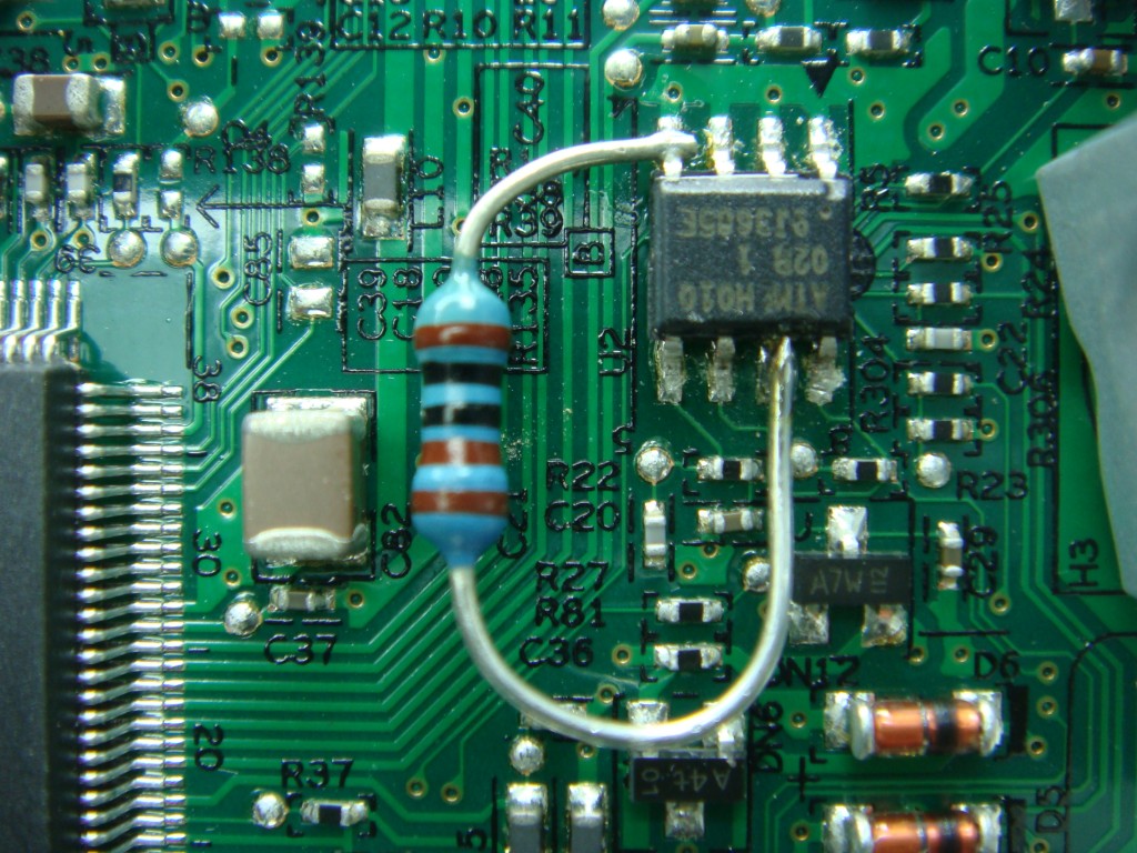
The EDID is stored on an I2C EEPROM. With a little bit of intuition you can make out where it is on the driver board. There should be an EEPROM for every input to the monitor, as each input has it’s own EDID. On mine there was an Atmel 24C02B 2k EEPROM next to the DVI connector. I used a meter to verify the clock and data pins connection to the DVI connector. From the datasheet, pin 7 is the write protect pin of the EEPROM. It is active high, so you need to desolder the pin and use a resistor to pull the pin to ground.

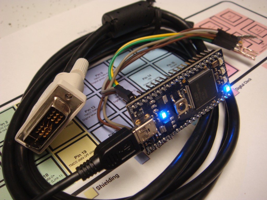
Now that the write protection is permanently disabled, you can write to the EDID directly over the I2C bus. To interface with the monitor, cut the end off of an old DVI cable. Use a meter to find the I2C clock and data lines. You will also want to find +5V and ground (pin 14 & 15). I then connected those pins to the corresponding pins on my mbed.
The reason I used my mbed was because there is a pre-written mbed program (I2C debug for RealTerm) that uses the I2C GUI buttons in realterm. I use realterm exclusively as my terminal program, it’s absolutely excellent for blindly hacking a serial interface. So it was an easy choice.
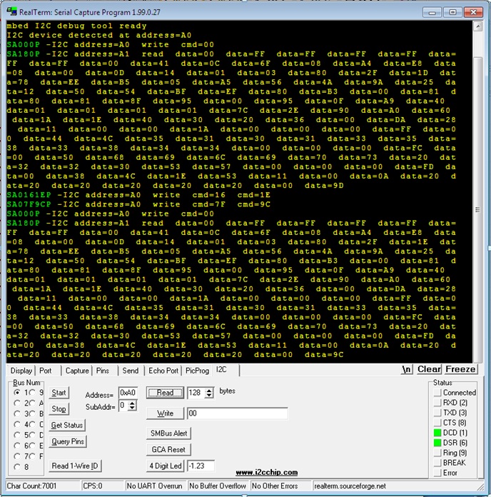
Import the I2C debug program into the mbed editor, and then compile it and save it to the mbed. Open realterm and set it to 9600,8,N,1 on the virtual COM port your mbed uses (you may have to install the driver for this). Connect the DVI cable to the monitor (double-check your power lines first!) and reset the mbed. The mbed should tell you in realterm that it is ready and found a device at address A0 or something similar. You can now send and receive commands via the interface. Refer to the datasheet for your particular EEPROM, but all I had to do to overwrite values was write the address and the new byte value in the “write” box. My monitor needed to be corrected from 1D (290mm vertical) to 1E (300mm vertical). Remember that changing a value will require re-calculation of the checksum. If you are just changing one value, it’s easy to just add or subtract the checksum with the amount you changed the other value by. In my case I added 1 so I subtracted 1 from the checksum. If you are doing a more significant edit, just import your EDID values into excel. You can then convert the values to decimal, sum the values and perform a modulus by 256. You should get zero as the result. The checksum makes the sum of the 128 byte EDID equal to zero. If you don’t get zero then modify the checksum until you do. If your checksum is incorrect it won’t be accepted by windows, which will label it in the registry as “BAD_EDID” if I remember right. When you’re done writing the new values, write an address of 0x00 and the read out 128 bytes. Verify your data. Your done!

1 Comment to Flash a monitor’s EDID with an mbed and RealTerm
Leave a Reply
Other Stuff
Recent Posts
- 6CY7 dual triode valve amplifier
- Air quality sensor (TVOC and eqCO2)
- Automotive rear fill “surround sound” with Boss DD-3
- Spring tester / weight scale
- Ducati 749/999 Tail Light
- Instruments for the GSXR
- Light pipe tail light for the GSXR
- M17x 6990m / 6970m overheating
- PAR / Spectrum analyzer
- Acrylic polishing and scratch removal
Archives
- May 2019 (2)
- April 2017 (3)
- October 2015 (1)
- May 2015 (1)
- March 2014 (2)
- December 2013 (1)
- July 2013 (1)
- November 2012 (1)
- October 2012 (4)
- September 2012 (1)
- August 2012 (3)
- June 2012 (1)
- March 2012 (1)
- February 2012 (1)
- January 2012 (1)
- October 2011 (3)
- July 2011 (1)
- June 2011 (3)
- May 2011 (2)
- April 2011 (1)
- December 2010 (1)
- August 2010 (1)
- July 2010 (3)
- April 2010 (2)
- March 2010 (2)
- January 2010 (2)
- December 2009 (2)
- October 2009 (2)
- September 2009 (1)
- August 2009 (15)
I’m about to try this method when i get home, though I’ve been trying to find a full version of powerstrip, but can’t find one that works with my video card