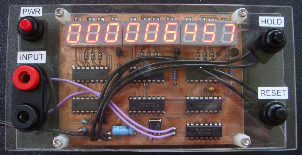
Build a 9-digit Pulse Counter for under $20
Recently I was fixing a piece of equipment and wanted a pulse counter to verify a stepper motor system. The existing linear slide was failing, but had a non-standard TPI. The step output was already programmed into a PLC. I had a programmable motor drive, but needed to know how many steps were commanded for a given linear move so I could electronically gear the system to a new linear slide.

That’s when I found the MC14453 3-digit BCD counter from ON semiconductor. ON semi has integrated three decade counters with an oscillator that multiplexes the 3 digits of an LED display. You pair it with an MC14543 7-segment decoder to have a three segment counter. You can cascade as many of these two chips as necessary by using the overflow output to clock the next stage, and feeding the first scan clock to the next multiplexer. I made a 9-digit counter, but you can do any multiple of three.
I used a MAX232 to drive the input of the counter. It’s a bit of a waste of the MAX232’s abilities, but the MAX232 does a great job of handling a wide range of input signals and it’s only about a buck. The chip can handle inputs from +30V to -30V, and still triggers between .5 and 1.5V with a 5V digital output. It also offers +/-15kV ESD protection on the inputs. With this capability you can sample a variety of different signals without any level shifting (even AC). With a few more input components (current limit resistor, zener clamp, series capacitor) you could capacitively couple the signal and measure anything. I wanted good low frequency performance so I skipped that part.
The parts cost about $6 per 3-digit stage. They are all available at Digi-Key. Part numbers:
MC14453: MC14553BCPGOS-ND
MC14543: MC14543BCPGOS-ND
MAX232: 296-6940-5-ND
7-Seg display: 160-1544-5-ND
The only problem with this arrangement is that the MC14543 is driving the LED segments, so it’s limited to less than 10mA drive current. That makes the segments a bit dimmer than I’d like for easy viewing. If I was doing it again I’d get some cheap transistors to run more current. The display is capable of 20mA.
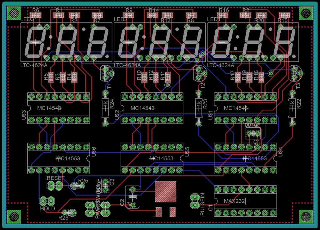
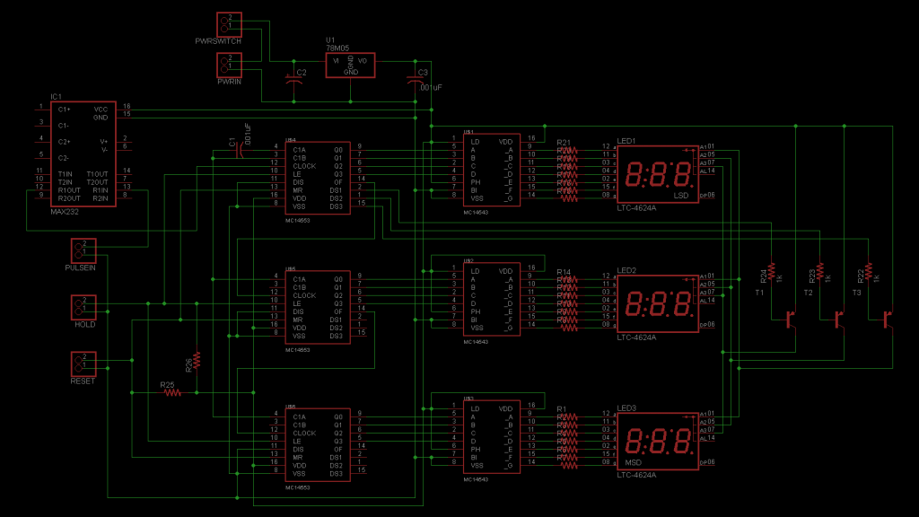
The schematic can be found in the datasheet for the MC14553. Keep reading for the layout and schematic for my build.
Click images for full-size. I mixed up the bias for the hold and reset inputs, if you use momentary off-on switches replace reset with R25 and hold with R26. Otherwise make sure the switches are normally closed.
21 Comments to Build a 9-digit Pulse Counter for under $20
Leave a Reply
Other Stuff
Recent Posts
- 6CY7 dual triode valve amplifier
- Air quality sensor (TVOC and eqCO2)
- Automotive rear fill “surround sound” with Boss DD-3
- Spring tester / weight scale
- Ducati 749/999 Tail Light
- Instruments for the GSXR
- Light pipe tail light for the GSXR
- M17x 6990m / 6970m overheating
- PAR / Spectrum analyzer
- Acrylic polishing and scratch removal
Archives
- May 2019 (2)
- April 2017 (3)
- October 2015 (1)
- May 2015 (1)
- March 2014 (2)
- December 2013 (1)
- July 2013 (1)
- November 2012 (1)
- October 2012 (4)
- September 2012 (1)
- August 2012 (3)
- June 2012 (1)
- March 2012 (1)
- February 2012 (1)
- January 2012 (1)
- October 2011 (3)
- July 2011 (1)
- June 2011 (3)
- May 2011 (2)
- April 2011 (1)
- December 2010 (1)
- August 2010 (1)
- July 2010 (3)
- April 2010 (2)
- March 2010 (2)
- January 2010 (2)
- December 2009 (2)
- October 2009 (2)
- September 2009 (1)
- August 2009 (15)


[…] to reverse engineer a stepper motor on a linear actuator that he was repairing, so he built this 9-digit pulse counter to keep track of how the motor was being controlled. It's a pretty standard circuit, however his […]
[…] roughly $20 to build, this 9 digit pulse counter is an excellent example of home built tools. The builder, [Josh] found himself repairing a device […]
[…] to reverse engineer a stepper motor on a linear actuator that he was repairing, so he built this 9-digit pulse counter to keep track of how the motor was being controlled. It’s a pretty standard circuit, however […]
so what is this “strobe” lead in the schmatic and where do i wire “hold” ?
The “strobe” signal is the input latch enable, or LE on the schematic. It’s normally low. When taken high, the latches hold the last value of the counters. This value is sent to the display multiplexer. Note that the counters can continue to count, but the display will retain the number of counts at the time LE went high. When LE returns low, the latches will display the actual value of the counter, which may have increased while the display was holding, if it was receiving clock inputs.
If you want to prevent pulses from actually reaching the counter instead of just pausing the display, use the “disable” line. Pulling this line high will ignore pulses sent to the clock input.
You can wire “hold” to either one as desired.
[…] roughly $20 to build, this 9 digit pulse counter is an excellent example of home built tools. The builder, [Josh] found himself repairing a device […]
[…] at $20 to build? This 9 digit pulse counter is an excellent example of home built tools. Josh, The builder found himself repairing a device and […]
[…] a 9-digit Pulse Counter – [Link] Tags: Counter, displays, MC14453 Filed in Test/Measurements | 1 views No Comments […]
[…] Build a 9-digit Pulse Counter – [Link] […]
Hello
Where do I get a PCB for this counter? Thanks
Do you have a PCB available for this circuit?
I just updated the post to include my schematic and PCB layout. I don’t have any finished PCBs, pretty much everything I make is one-off. Maybe when I’m done with school I’ll have time to make batches.
Thank you! What Layout/Schematic software do you use? I’ve never found one with components like the LED displays.
I use EagleCAD. Eagle has LED 7-segment components, but I had to make the three digit part in my library. With Eagle you just set up your own library and then make any components that aren’t in Eagle’s library.
I have two goals. 1.Build this as a learning experience. 2
Use the counter to count pulses generated by a Mercedes diagnostic trouble code provision on pre 1996 model vehicles. I have electrical skills but no experience with building this sort of thing. Any tips would be greatly appreciated. Thanks
Start with the datasheet for the two chips. The schematic is there. Then decide if you are going to breadboard it, or maybe use perfboard if you can’t etch your own boards. Wire it up just like in the schematic. The MAX232 also has a schematic in the datashseet. The output of that chip is the input to the counter. The MAX232 buffers the signal and protects the counters from voltage spikes. You can wire the Merc’s diagnostic wire to the input of the MAX232 and it will trigger as long as the signal crosses approximately 2.5V. Good luck.
Thanks for your help! This will be fun
[…] to reverse engineer a stepper motor on a linear actuator that he was repairing, so he built this 9-digit pulse counter to keep track of how the motor was being controlled. It’s a pretty standard circuit, however […]
what are the values of components needed here????
Can it be “converted” into a 1hz resolution frequency counter?
any hints?
This is a great device! I found some more information on this website: http://www.directindustry.com/industrial-manufacturer/counter-61022.html