PCB layouts and schematics for my CNC
I’ve received some email and comment requests for the layouts and schematics of the electronics running my CNC machine. I’ve pulled together what I can find for this article.
Power Filter Boards
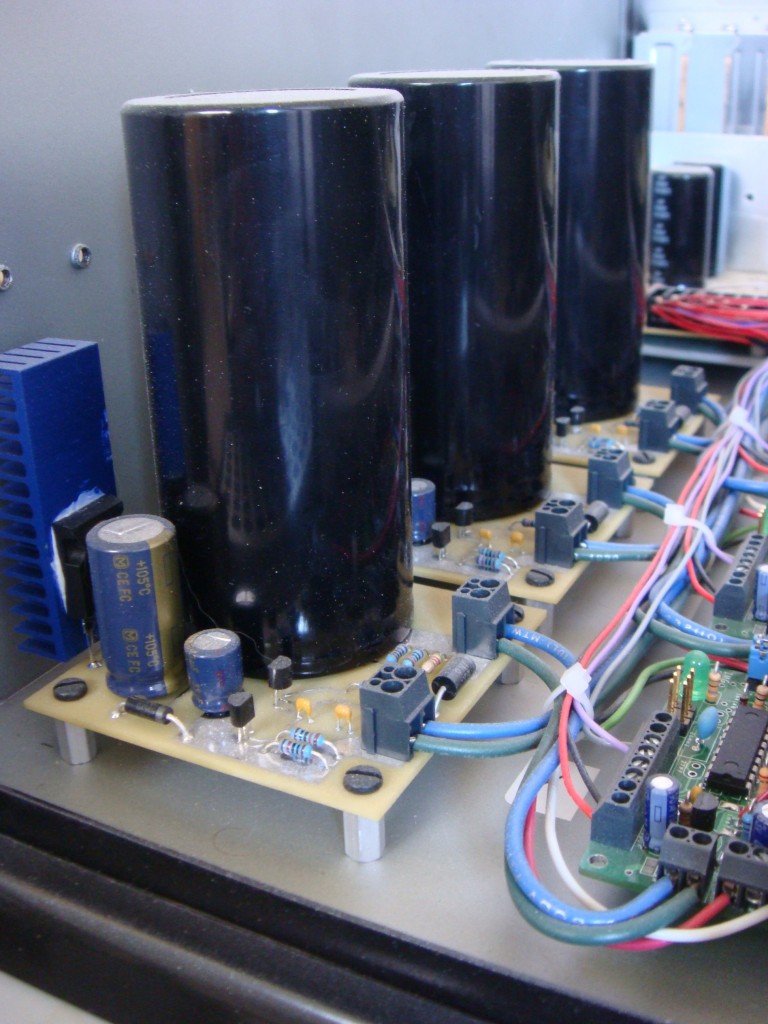
I made these power filters for a few reasons. One is to protect the stepper motor drives from the inductive spikes that can come off of the motors. They can be pretty big. Another reason was that I wanted to use a switch-mode power supply to run the drives. There’s a lot of good reasons for this:
1. Switch-mode power supplies are cheaper than linear power supplies.
2. Switch-mode power supplies are smaller than linear supplies for equivalent output power.
3. Switch-mode power supplies come in a wide range of voltages, so you can run the stepper motors at the highest voltage possible. (The highest voltage your controller supports) This allows for more torque from any motor because a higher voltage will push more current through the inductance of the motor than a lower voltage. It will also do it quicker, so you should get a little more speed too.
However, I wasn’t sure that the chopper-style stepper driver would be okay with a switch mode supply, as it pretty much shorts out the supply every time the chopper turns on. So I needed a buffer.
I found this article at EETimesAsia by John Betten from TI. I modified the circuit for the voltage levels I wanted to run, and also found a suitable replacement for the FET since I couldn’t find one at the time. Here is the original schematic:
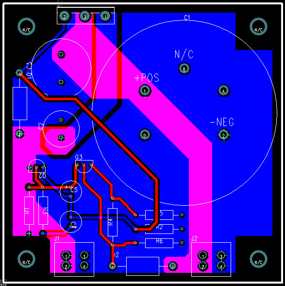
I’m using an IR IRFP9140N in place of Q1. I also replaced D2 with a 56V TVS from ON semi, 1.5KE56A. I used 56V because the LMD18245 motor driver IC I have has a continuous rating of 55V and an absolute max of 60V. I also oversized the output capacitor just to be on the safe side since I had some big ones laying around anyway. They are 22000uF 100V Panasonics. They are overkill, the voltage is rock-solid even when the motors are running at full clip. I wanted to be able to recycle the boards though if I ever upgrade to a bigger machine and have bigger motors. Here’s the layout for my circuit:
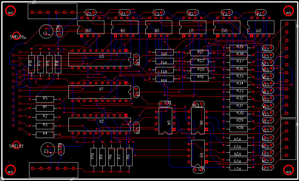
Opto-isolated Parallel Interface Board
I designed this parallel interface board after killing a parallel port with a breakout board that I bought off the internet. I think it just pulled too much current from the port. I designed this board to pull the smallest amount of current from the parallel port as possible, while also providing good drive characteristics for outputs. This board is customized to my application, so the voltages and bias might not be appropriate for all. Check to make sure your inputs will work before using the values here. I couldn’t find the schematic, just the layout but it’s not too complicated to figure out if you have the datasheets for the TLP2631 and the SN74LS244N.
The 74244 is just a buffer; high impedance inputs and good drive characteristics. All inputs and outputs have RC filters. Adjust these values to suit your application. The 2631 is an opto-isolator that keeps the PC’s voltage potentials isolated from the CNC machine’s voltage. That way no voltage spikes hit the PC and there are no ground loops with the power supplies. Complete isolation! You just have to run power over from a spare drive connector on the PC to wherever you put this board.
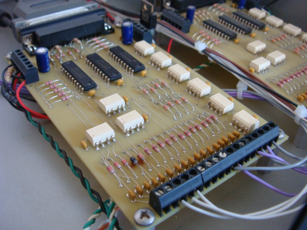
The astute observer will notice a fried resistor on the board. That’s the board doing just what it was designed to do, protect my computer from dumb screw-ups. I accidentally miswired one of my limit switches during the build and the little resistor took a hike. I could have just replaced the resistor, but I’m not using all of the inputs so I just moved the wire over and remapped the limit input pin. Here’s the layout. Click to view full size.
Stepper Motor Controller
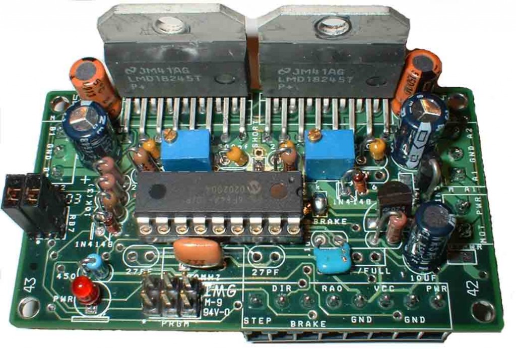
I used the “Microstep” from EAS Electronics. It’s worked well, but the switching frequency is low enough to create an obnoxious whine when the motors aren’t moving. I read in the LMD18245 datasheet that you can adjust the chopping frequency, but I haven’t bothered to try. It’ s loud enough anyway when my router “spindle” is turning that it’s not too important to me.
It’s PIC based and the source is available if you want to modify it to do custom stuff. The microstep ranges are 10,8,4,half, and full step.
My next machine will use Automation Direct’s stepper drivers. They aren’t as cheap as building your own, but they are pretty close. I used two of their STP-DRV-4035 drives in a project at work along with their stepper motors and was pleased with the results. If you need really fine step rate control, they have one that is programmable but it costs more.
5 Comments to PCB layouts and schematics for my CNC
Leave a Reply
Other Stuff
Recent Posts
- 6CY7 dual triode valve amplifier
- Air quality sensor (TVOC and eqCO2)
- Automotive rear fill “surround sound” with Boss DD-3
- Spring tester / weight scale
- Ducati 749/999 Tail Light
- Instruments for the GSXR
- Light pipe tail light for the GSXR
- M17x 6990m / 6970m overheating
- PAR / Spectrum analyzer
- Acrylic polishing and scratch removal
Archives
- May 2019 (2)
- April 2017 (3)
- October 2015 (1)
- May 2015 (1)
- March 2014 (2)
- December 2013 (1)
- July 2013 (1)
- November 2012 (1)
- October 2012 (4)
- September 2012 (1)
- August 2012 (3)
- June 2012 (1)
- March 2012 (1)
- February 2012 (1)
- January 2012 (1)
- October 2011 (3)
- July 2011 (1)
- June 2011 (3)
- May 2011 (2)
- April 2011 (1)
- December 2010 (1)
- August 2010 (1)
- July 2010 (3)
- April 2010 (2)
- March 2010 (2)
- January 2010 (2)
- December 2009 (2)
- October 2009 (2)
- September 2009 (1)
- August 2009 (15)
Hi: Dear
Thank you very good site
Do you interface with the Mach 3 works
Is it possible for me to email it to Schematic
Sincerely: Nasser
Thanks. It does interface with Mach3, as well as TurboCNC. Mach3 has better support for PCI parallel port cards though, you can use addresses other than legacy addresses. So motor step/direction signals are on LPT1 (378 or whatever) and the extra stuff like limit and home switches is on the external parallel port card. That way I can use both programs but Mach3 also has limit, home, interlocks, spindle on/off, etc.
Sorry, I don’t have the file anymore so I can’t send it to you.
What is the value of resistors and capacitors on Opto-isolated Parallel Interface Board ?
thanks
FYI, I think Automation Direct’s STP-DRV-4035 drivers are actually Applied Motion Products’ 3540M drivers.
http://www.applied-motion.com/products/stepper-drives/3540m
Thanks for the tip. I’ve been suspicious about Automation Direct’s drives, because they look exactly like the Applied Motion products that omega sells for three times the price. I’m hoping there’s a difference.