Build a spot welder from a battery charger
I ran across a battery charger a while ago that was collecting dust. I looked inside and saw the transformer, heatsinks, high current bridge rectifier and SCR and knew I could do something with it. So I turned it into a spot welder.
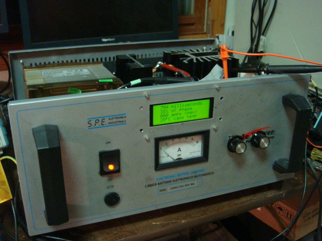
I originally intended this project to weld thin sheetmetal tabs to stuff to act as solder tabs. The project has not been as easy as I originally thought though. (It also suffered some scope creep) It’s my first crack at 5V logic mixed with line AC voltage, and for rolling my own power supply. I used a step-down transformer, bridge regulator and a capacitor to feed an LDO regulator for the control circuit. With the low current draw of the controller, the voltage input to the regulator was relatively free from any ripple thanks to the capacitor.
I ended up frying a processor, LCD, and a couple other components due to a dumb move while troubleshooting the circuit, and overlooking a capacitor’s voltage rating. 120VAC will eat 5V stuff for lunch.
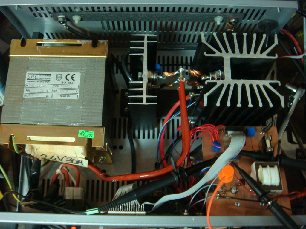
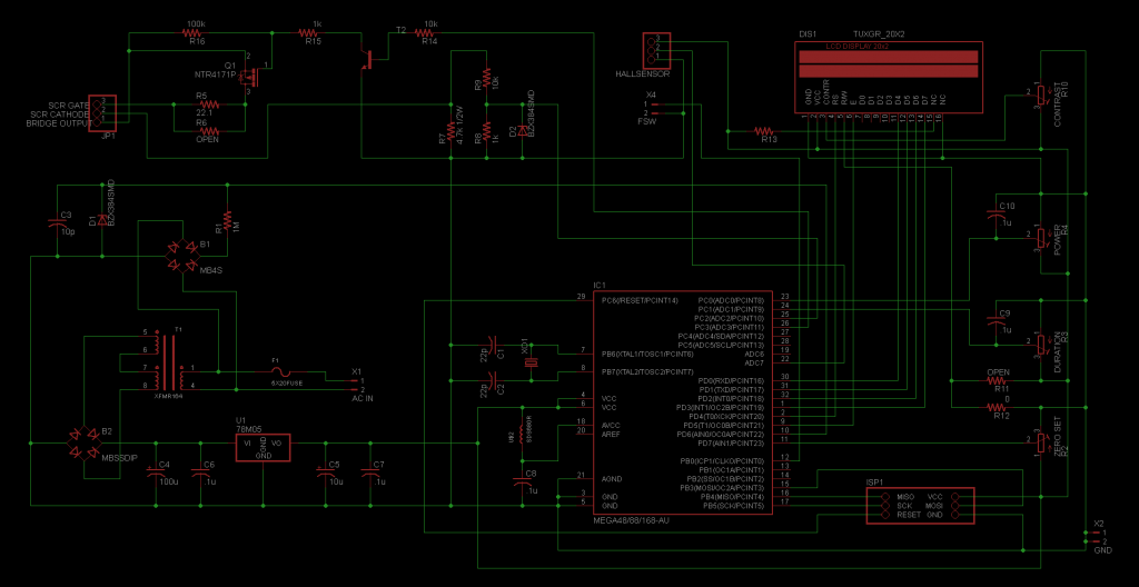
The control circuit basically modulates the SCR, which is hooked up to the output of the bridge rectifier after a step-down transformer. The controller allows for adjustment of duration of the weld and amount of the rectified AC phase that is delivered to the workpiece. The controller holds off the SCR until a pre-determined time of each half phase to control power delivery. An analog comparator detects the zero point of the phase for timing purposes, via a seperate bridge rectifier that has it’s ouput fed through a large resistor to the comparator. A zener clamps the current-limited voltage at 4.8V so as not to damage the micro’s input. A high-to-low transition on the comparator triggers the zero crossing timer. The threshhold voltage is adjustable by an on-board pot.
I also added an Allegro hall effect current sensor that I had lying around from my alternator current sense project. It’s overkill, but it measures the amount of peak current being delivered and displays it on the LCD.
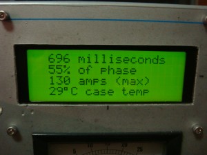
The controller is an ATmega88PA running at 8Mhz. Firmware is written in C with AVRStudio and AVR-GCC. The micro reads the power and duration settings, displays that on the LCD, along with the max current for the last weld cycle and the temperature of the mega’s on-chip sensor. The controller also handles timing duties, zero crossing detection, and control of the SCR gate. The gate is fired by a P-channel MOSFET, with the FET’s gate driven by an NPN BJT on one of the micro’s pins. A footswitch is used as input to the micro to trigger a weld cycle. Both the footswitch input and the zero crossings are buffered by a simple three-sample debouncing routine to prevent erroneous triggers. The system also checks for the footswitch input on power up and after the weld cycle is complete, and waits if the footswitch is down with a message on the LCD to release the footswitch. This allows for safety as well as eliminating any unintended re-triggers at very short durations. Duration is adjustable from roughly one ac cycle to 60 cycles (1 sec). Power control allows from 5% to 95% of each half phase to be delivered to the workpiece.
The SCR’s cathode voltage is available at PORTC2 as a 10:1 voltage divider, and clamped with a zener to prevent damage to the micro. I didn’t need it, so it’s not used in the code.
I’ve also added a power resistor to the output to limit current. I used carbon-carbon as a power resistor (I work in a carbon plant) since it’s free and power resistors are expensive. You only need a few tenths of an ohm to limit the current to a level that won’t destroy the diodes and SCR. I’m overdriving mine at about 130A maximum. It seems to handle it fine for the short bursts. [Edit: 130A isn’t enough though. I may rewire so the diodes/SCR are on the input side and push the current higher by removing or modifying the resistor. Pressure of the electrodes on the joint is also important, still figuring that out.]
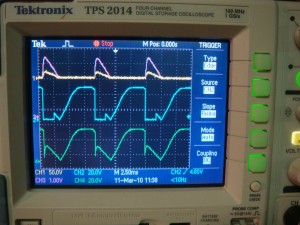
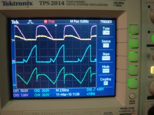
Here’s some drive waveforms: yellow is the output voltage (it’s at 50V/div so it looks small), purple is the output current measured by the hall sensor, blue is the FET’s gate that turns on the SCR, and green is the bridge voltage.
This project has got me thinking about modifying my old “buzzbox” AC welder. I’ve got some big capacitors and IGBTs from a couple old motor drives that could give me a really nice TIG welding power supply. I think I’ve read you can weld high frequency (1-2kHz?) square-wave without needing any HF section. If I remember right square-wave with a positive DC offset is sort of the ultimate TIG welder. Anybody with comments or information about that feel free to drop me a line.
Continue reading for the schematic, PCB layout, and code.
References: Miller Resistance Spot Welding
The schematic: (Click on the picture for full size)
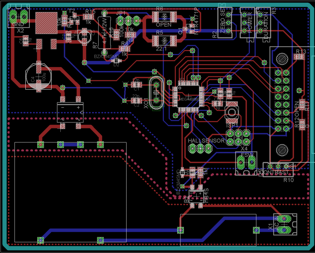
The board: (Click for full-size image)
And the code. I think it’s all correct but I had to rewire a couple things on mine so you might do well to doublecheck the I/O is all correct.
——————————————————————————————————————————
#include <avr/io.h>
#include <util/delay.h>
#include <avr/interrupt.h>
//#include <avr/wdt.h> // can’t get the watchdog to work yet
#define F_CPU 8000000; //8MHz
//function declarations
void lcd_write_byte(unsigned char CONTROL, unsigned char DATA);
void initLCD(void);
void updateLCD(void);
void switch_up(void);
void weld_message(void);
//global variables
volatile unsigned int power, duration, temperature;
volatile unsigned char current, max_current;
void main(void)
{
unsigned int old_power, old_duration= 0; //variables for comparison
PRR &= ~(1<<PRADC); //disable ADC power reduction
ADMUX |= (1<<REFS0); //setup VCC as reference
ADMUX |= (1<<ADLAR); //left adjust result for 8 bit ADC
ADCSRA |= (1<<ADPS0)|(1<<ADPS1)|(1<<ADPS2); //prescaler clk/64 125kHz @ 8MHz clock
ADCSRA |= (1<<ADEN); //enable ADC
TCCR1B |= (1<<CS10); //enable timer1, no prescale (clk/1)
ACSR |= (1<<ACIS1); //enable analog comparator falling edge interrupt
ACSR |= (1<<ACIE); //enable analog comparator interrupt
DDRC |= (1<<PORTC3); //SCR gate drive
DDRC &= ~((1<<PORTC0)|(1<<PORTC1)|(1<<PORTC2)); //set as input
PORTC &= ~((1<<PORTC0)|(1<<PORTC1)|(1<<PORTC2)); //PUD
DDRD |= (1<<PORTD0)|(1<<PORTD1)|(1<<PORTD2)|(1<<PORTD3)|(1<<PORTD4)|(1<<PORTD5);
DDRD &= ~((1<<PORTD6)|(1<<PORTD7)); //set as input
PORTD &= ~((1<<PORTD6)|(1<<PORTD7)); //PUD
DDRB &= ~(1<<PORTB0); //footswitch input
PORTB &= ~(1<<PORTB0); //PUD
initLCD(); //set up LCD
switch_up(); //check footswitch
max_current= 0x7F;
updateLCD(); //display settings
// wdt_reset(); //reset the watchdog timer
// WDTCSR |= (1<<WDCE)|(1<<WDE); //clear the system reset/ change enable bits
// WDTCSR |= (1<<WDE)|(1<<WDP0)|(1<<WDP1)|(1<<WDP2); //set new prescaler, 2 seconds
while(1)
{
old_power= power; //set up the comparsison value before getting new value
ADMUX &= ~((1<<MUX0)|(1<<MUX1)|(1<<MUX2)|(1<<MUX3)); //sample ADC0 (power setting)
ADCSRA |= (1<<ADSC); //start conversion
while(ADCSRA & (1<<ADSC)){} //wait for conversion
power= ADCH;
power*= 234; //scale power for use later: ((2^8)*234)= 59904 max value
//59904 clk cycles= (1/8000000)*59904= 7.5ms
//7.5ms= (.0075/(1/120))*100= 90% of one half wave (60Hz)
//with these values power can be up to 90% of each half wave,
//which with the 5% coded into the ISR, yields a range of 5%-95%.
old_duration= duration; //set up the comparsison value before getting new value
ADMUX |= (1<<MUX0); //sample ADC1 (duration setting)
ADCSRA |= (1<<ADSC); //start conversion
while(ADCSRA & (1<<ADSC)){} //wait for conversion
duration= ADCH;
duration= (duration>>1); //convert to 7-bit number, limits duration to ~1 second
if(duration<=0x0007) duration= 0x0000;
else duration-= 0x0007; //subtract 7 so duration can’t exceed 3 digits (999ms)
ADMUX &= ~((1<<MUX0)|(1<<MUX1)|(1<<MUX2)); //set up for ADC8 (temp)
ADMUX |= (1<<MUX3);
ADMUX |= (1<<REFS0)|(1<<REFS1); //1.1V ADC reference
ADMUX &= ~(1<<ADLAR); //undo left adjust result for 8 bit ADC
ADCSRA |= (1<<ADSC); //start conversion
while(ADCSRA & (1<<ADSC)){} //wait for conversion
temperature= ADC;
temperature/= 12; //scale temp value to degrees C
ADMUX |= (1<<ADLAR); //restore left adjust result
ADMUX &= ~(1<<REFS1); //restore VCC ADC reference
if(power!=old_power) updateLCD(); //update LCD if values changed
else if(duration!=old_duration) updateLCD();
if((!(PINB & (1<<PINB0))) & (duration>0)) //check for footswitch input
{
char j= 0;
for(j= 0;j< 3;) //three sample noise filter
{
if(!(PINB & (1<<PINB0))) j++; //increment loop value if PORTC2 (fsw) is low
else j= 4; //break out of the loop if high
}
if(j==3) //should only get here if we got three low samples
{
weld_message();
ADMUX |= (1<<MUX0)|(1<<MUX1)|(1<<MUX2); //sample ADC7 (current sensor)
ADMUX &= ~(1<<MUX3);
ADCSRA |= (1<<ADATE); //ADC free runnnng mode
ADCSRA |= (1<<ADSC); //start conversion
_delay_us(5); //wait for ADC’s first reading
max_current= 0x0000; //reset max current from last cycle
sei();
while((!(PINB & (1<<PINB0))) & (duration>0)){} //wait for zero cross
cli();
ADCSRA &= ~(1<<ADATE); //turn off free running
switch_up(); //wait for footswitch release
updateLCD();
}
}
}
}
ISR (ANALOG_COMP_vect)
{
char i= 0;
for(i= 0;i< 3;) //three sample noise filter
{
if(!(ACSR & (1<<ACO))) i++; //increment loop value if ACO is low
else i= 4; //break out of the loop if high
}
if(i==3) //should only get here if we got three low samples,
{ //which indicates a zero crossing.
TCNT1= 0;
while(TCNT1< power){} //wait for phase rotation
PORTC |= (1<<PORTC3); //fire SCR
while(TCNT1< 63333) //wait for 7.9ms, 95% of one half cycle (60Hz)
{
current= ADCH;
if(current>max_current) max_current= current; //record the highest value
}
PORTC &= ~(1<<PORTC3); //turn off SCR gate
duration–;
}
}
void initLCD(void)
{
_delay_ms(250); // Wait for HD44780
PORTD &= ~(1<<PORTD4);
PORTD |= (1<<PORTD1);
PORTD |= (1<<PORTD0);
PORTD |= (1<<PORTD5); // function set
_delay_ms(2);
PORTD &= ~(1<<PORTD5);
_delay_ms(20);
PORTD |= (1<<PORTD5); // function set
_delay_ms(2);
PORTD &= ~(1<<PORTD5);
_delay_ms(10);
PORTD |= (1<<PORTD5); // function set
_delay_ms(2);
PORTD &= ~(1<<PORTD5);
_delay_ms(10);
PORTD &= ~(1<<PORTD0);
PORTD |= (1<<PORTD5); // initialize to 4 bit
_delay_ms(2);
PORTD &= ~(1<<PORTD5);
_delay_ms(10);
lcd_write_byte(0,0×28); //set interface width, # of lines, and font size
lcd_write_byte(0,0x0C); //display on
lcd_write_byte(0,0×01); //clear display
lcd_write_byte(0,0×06); //increment address by one, shift cursor at write
}
void lcd_write_byte(unsigned char CONTROL, unsigned char DATA)
{
if(CONTROL == 1) PORTD |= (1<<PORTD4); else PORTD &= ~(1<<PORTD4);
if((DATA & 0x80) == 0x80) PORTD |= (1<<PORTD3); else PORTD &= ~(1<<PORTD3);
if((DATA & 0x40) == 0x40) PORTD |= (1<<PORTD2); else PORTD &= ~(1<<PORTD2);
if((DATA & 0x20) == 0x20) PORTD |= (1<<PORTD1); else PORTD &= ~(1<<PORTD1);
if((DATA & 0x10) == 0x10) PORTD |= (1<<PORTD0); else PORTB &= ~(1<<PORTD0);
PORTD |= (1<<PORTD5);
_delay_ms(1);
PORTD &= ~(1<<PORTD5);
if((DATA & 0x08) == 0x08) PORTD |= (1<<PORTD3); else PORTD &= ~(1<<PORTD3);
if((DATA & 0x04) == 0x04) PORTD |= (1<<PORTD2); else PORTD &= ~(1<<PORTD2);
if((DATA & 0x02) == 0x02) PORTD |= (1<<PORTD1); else PORTD &= ~(1<<PORTD1);
if((DATA & 0x01) == 0x01) PORTD |= (1<<PORTD0); else PORTD &= ~(1<<PORTD0);
PORTD |= (1<<PORTD5);
_delay_ms(2);
PORTD &= ~(1<<PORTD5);
_delay_ms(10);
}
void updateLCD(void)
{
unsigned int temp_duration, temp_power, temp_max_current;
temp_duration= (duration*8); //scale duration for BCD conversion to milliseconds //
unsigned int duration_BCD= ((((temp_duration/10)+((temp_duration/100)*6))*16)+(temp_duration%10));
unsigned char ONES= 0x00;
unsigned char TENS= 0x00;
unsigned char HUND= 0x00;
if((duration_BCD & 0x0800) == 0x0800) HUND |= 0x08; else HUND &= ~0x08;
if((duration_BCD & 0x0400) == 0x0400) HUND |= 0x04; else HUND &= ~0x04;
if((duration_BCD & 0x0200) == 0x0200) HUND |= 0x02; else HUND &= ~0x02;
if((duration_BCD & 0x0100) == 0x0100) HUND |= 0x01; else HUND &= ~0x01;
if((duration_BCD & 0x0080) == 0x0080) TENS |= 0x08; else TENS &= ~0x08;
if((duration_BCD & 0x0040) == 0x0040) TENS |= 0x04; else TENS &= ~0x04;
if((duration_BCD & 0x0020) == 0x0020) TENS |= 0x02; else TENS &= ~0x02;
if((duration_BCD & 0x0010) == 0x0010) TENS |= 0x01; else TENS &= ~0x01;
if((duration_BCD & 0x0008) == 0x0008) ONES |= 0x08; else ONES &= ~0x08;
if((duration_BCD & 0x0004) == 0x0004) ONES |= 0x04; else ONES &= ~0x04;
if((duration_BCD & 0x0002) == 0x0002) ONES |= 0x02; else ONES &= ~0x02;
if((duration_BCD & 0x0001) == 0x0001) ONES |= 0x01; else ONES &= ~0x01;
ONES |= 0x30;
TENS |= 0x30;
HUND |= 0x30;
lcd_write_byte(0x00, 0x01); //clear screen
lcd_write_byte(0x01, 0x20); //space
lcd_write_byte(0x01, 0x20); //space
lcd_write_byte(0x01, 0x20); //space
lcd_write_byte(0x01, HUND);
lcd_write_byte(0x01, TENS);
lcd_write_byte(0x01, ONES);
lcd_write_byte(0x01, 0x20); //space
lcd_write_byte(0x01, 0x6D); //’m’
lcd_write_byte(0x01, 0x69); //’i’
lcd_write_byte(0x01, 0x6C); //’l’
lcd_write_byte(0x01, 0x6C); //’l’
lcd_write_byte(0x01, 0x69); //’i’
lcd_write_byte(0x01, 0x73); //’s’
lcd_write_byte(0x01, 0x65); //’e’
lcd_write_byte(0x01, 0x63); //’c’
lcd_write_byte(0x01, 0x6F); //’o’
lcd_write_byte(0x01, 0x6E); //’n’
lcd_write_byte(0x01, 0x64); //’d’
lcd_write_byte(0x01, 0x73); //’s’
temp_power= (power/665); //scale power for BCD conversion to percent
temp_power=(95-temp_power);
unsigned int power_BCD= ((temp_power/10)*16)+(temp_power%10);
ONES= 0x00;
TENS= 0x00;
if((power_BCD & 0x0080) == 0x0080) TENS |= 0x08; else TENS &= ~0x08;
if((power_BCD & 0x0040) == 0x0040) TENS |= 0x04; else TENS &= ~0x04;
if((power_BCD & 0x0020) == 0x0020) TENS |= 0x02; else TENS &= ~0x02;
if((power_BCD & 0x0010) == 0x0010) TENS |= 0x01; else TENS &= ~0x01;
if((power_BCD & 0x0008) == 0x0008) ONES |= 0x08; else ONES &= ~0x08;
if((power_BCD & 0x0004) == 0x0004) ONES |= 0x04; else ONES &= ~0x04;
if((power_BCD & 0x0002) == 0x0002) ONES |= 0x02; else ONES &= ~0x02;
if((power_BCD & 0x0001) == 0x0001) ONES |= 0x01; else ONES &= ~0x01;
ONES |= 0x30;
TENS |= 0x30;
lcd_write_byte(0x00, 0xC0); //go to second line
lcd_write_byte(0x01, 0x20); //space
lcd_write_byte(0x01, 0x20); //space
lcd_write_byte(0x01, TENS);
lcd_write_byte(0x01, ONES);
lcd_write_byte(0x01, 0x25); //’%’
lcd_write_byte(0x01, 0x20); //space
lcd_write_byte(0x01, 0x6F); //’o’
lcd_write_byte(0x01, 0x66); //’f’
lcd_write_byte(0x01, 0x20); //space
lcd_write_byte(0x01, 0x70); //’p’
lcd_write_byte(0x01, 0x68); //’h’
lcd_write_byte(0x01, 0x61); //’a’
lcd_write_byte(0x01, 0x73); //’s’
lcd_write_byte(0x01, 0x65); //’e’
temp_max_current= max_current;
temp_max_current-= 0x7F; //remove 2.5V sensor offset
temp_max_current*= 3; //scaling
temp_max_current/= 2; //scaling
unsigned int max_current_BCD= ((((temp_max_current/10)+((temp_max_current/100)*6))*16)+(temp_max_current%10));
ONES= 0x00;
TENS= 0x00;
HUND= 0x00;
if((max_current_BCD & 0x0800) == 0x0800) HUND |= 0x08; else HUND &= ~0x08;
if((max_current_BCD & 0x0400) == 0x0400) HUND |= 0x04; else HUND &= ~0x04;
if((max_current_BCD & 0x0200) == 0x0200) HUND |= 0x02; else HUND &= ~0x02;
if((max_current_BCD & 0x0100) == 0x0100) HUND |= 0x01; else HUND &= ~0x01;
if((max_current_BCD & 0x0080) == 0x0080) TENS |= 0x08; else TENS &= ~0x08;
if((max_current_BCD & 0x0040) == 0x0040) TENS |= 0x04; else TENS &= ~0x04;
if((max_current_BCD & 0x0020) == 0x0020) TENS |= 0x02; else TENS &= ~0x02;
if((max_current_BCD & 0x0010) == 0x0010) TENS |= 0x01; else TENS &= ~0x01;
if((max_current_BCD & 0x0008) == 0x0008) ONES |= 0x08; else ONES &= ~0x08;
if((max_current_BCD & 0x0004) == 0x0004) ONES |= 0x04; else ONES &= ~0x04;
if((max_current_BCD & 0x0002) == 0x0002) ONES |= 0x02; else ONES &= ~0x02;
if((max_current_BCD & 0x0001) == 0x0001) ONES |= 0x01; else ONES &= ~0x01;
ONES |= 0x30;
TENS |= 0x30;
HUND |= 0x30;
lcd_write_byte(0x00, 0x95); //go to third line (DDRAM address 0x15)
lcd_write_byte(0x01, 0x20); //space
lcd_write_byte(0x01, HUND);
lcd_write_byte(0x01, TENS);
lcd_write_byte(0x01, ONES);
lcd_write_byte(0x01, 0x20); //space
lcd_write_byte(0x01, 0x61); //’a’
lcd_write_byte(0x01, 0x6D); //’m’
lcd_write_byte(0x01, 0x70); //’p’
lcd_write_byte(0x01, 0x73); //’s’
lcd_write_byte(0x01, 0x20); //space
lcd_write_byte(0x01, 0x28); //'(‘
lcd_write_byte(0x01, 0x6D); //’m’
lcd_write_byte(0x01, 0x61); //’a’
lcd_write_byte(0x01, 0x78); //’x’
lcd_write_byte(0x01, 0x29); //’)’
unsigned int temperature_BCD= ((temperature/10)*16)+(temperature%10);
ONES= 0x00;
TENS= 0x00;
if((temperature_BCD & 0x0080) == 0x0080) TENS |= 0x08; else TENS &= ~0x08;
if((temperature_BCD & 0x0040) == 0x0040) TENS |= 0x04; else TENS &= ~0x04;
if((temperature_BCD & 0x0020) == 0x0020) TENS |= 0x02; else TENS &= ~0x02;
if((temperature_BCD & 0x0010) == 0x0010) TENS |= 0x01; else TENS &= ~0x01;
if((temperature_BCD & 0x0008) == 0x0008) ONES |= 0x08; else ONES &= ~0x08;
if((temperature_BCD & 0x0004) == 0x0004) ONES |= 0x04; else ONES &= ~0x04;
if((temperature_BCD & 0x0002) == 0x0002) ONES |= 0x02; else ONES &= ~0x02;
if((temperature_BCD & 0x0001) == 0x0001) ONES |= 0x01; else ONES &= ~0x01;
ONES |= 0x30;
TENS |= 0x30;
lcd_write_byte(0x00, 0xD5); //go to fourth line (DDRAM address 0x55)
lcd_write_byte(0x01, 0x20); //space
lcd_write_byte(0x01, TENS);
lcd_write_byte(0x01, ONES);
lcd_write_byte(0x01, 0xDF); //degree symbol
lcd_write_byte(0x01, 0x43); //’C’
lcd_write_byte(0x01, 0x20); //space
lcd_write_byte(0x01, 0x63); //’c’
lcd_write_byte(0x01, 0x61); //’a’
lcd_write_byte(0x01, 0x73); //’s’
lcd_write_byte(0x01, 0x65); //’e’
lcd_write_byte(0x01, 0x20); //space
lcd_write_byte(0x01, 0x74); //’t’
lcd_write_byte(0x01, 0x65); //’e’
lcd_write_byte(0x01, 0x6D); //’m’
lcd_write_byte(0x01, 0x70); //’p’
}
void switch_up(void)
{
if(!(PINB & (1<<PINB0)))
{
lcd_write_byte(0x00, 0x01); //clear screen
lcd_write_byte(0x01, 0x20); //space
lcd_write_byte(0x01, 0x20); //space
lcd_write_byte(0x01, 0x72); //’r’
lcd_write_byte(0x01, 0x65); //’e’
lcd_write_byte(0x01, 0x6C); //’l’
lcd_write_byte(0x01, 0x65); //’e’
lcd_write_byte(0x01, 0x61); //’a’
lcd_write_byte(0x01, 0x73); //’s’
lcd_write_byte(0x01, 0x65); //’e’
lcd_write_byte(0x01, 0x20); //space
lcd_write_byte(0x01, 0x66); //’f’
lcd_write_byte(0x01, 0x6F); //’o’
lcd_write_byte(0x01, 0x6F); //’o’
lcd_write_byte(0x01, 0x74); //’t’
lcd_write_byte(0x01, 0x73); //’s’
lcd_write_byte(0x01, 0x77); //’w’
lcd_write_byte(0x01, 0x69); //’i’
lcd_write_byte(0x01, 0x74); //’t’
lcd_write_byte(0x01, 0x63); //’c’
lcd_write_byte(0x01, 0x68); //’h’
while(!(PINB & (1<<PINB0))){};
}
}
void weld_message(void)
{
lcd_write_byte(0x00, 0x01); //clear screen
lcd_write_byte(0x01, 0x20); //space
lcd_write_byte(0x01, 0x20); //space
lcd_write_byte(0x01, 0x77); //’w’
lcd_write_byte(0x01, 0x65); //’e’
lcd_write_byte(0x01, 0x6C); //’l’
lcd_write_byte(0x01, 0x64); //’d’
lcd_write_byte(0x01, 0x69); //’i’
lcd_write_byte(0x01, 0x6E); //’n’
lcd_write_byte(0x01, 0x67); //’g’
lcd_write_byte(0x01, 0x2E); //’.’
lcd_write_byte(0x01, 0x2E); //’.’
lcd_write_byte(0x01, 0x2E); //’.’
}
15 Comments to Build a spot welder from a battery charger
Leave a Reply
Other Stuff
Recent Posts
- 6CY7 dual triode valve amplifier
- Air quality sensor (TVOC and eqCO2)
- Automotive rear fill “surround sound” with Boss DD-3
- Spring tester / weight scale
- Ducati 749/999 Tail Light
- Instruments for the GSXR
- Light pipe tail light for the GSXR
- M17x 6990m / 6970m overheating
- PAR / Spectrum analyzer
- Acrylic polishing and scratch removal
Archives
- May 2019 (2)
- April 2017 (3)
- October 2015 (1)
- May 2015 (1)
- March 2014 (2)
- December 2013 (1)
- July 2013 (1)
- November 2012 (1)
- October 2012 (4)
- September 2012 (1)
- August 2012 (3)
- June 2012 (1)
- March 2012 (1)
- February 2012 (1)
- January 2012 (1)
- October 2011 (3)
- July 2011 (1)
- June 2011 (3)
- May 2011 (2)
- April 2011 (1)
- December 2010 (1)
- August 2010 (1)
- July 2010 (3)
- April 2010 (2)
- March 2010 (2)
- January 2010 (2)
- December 2009 (2)
- October 2009 (2)
- September 2009 (1)
- August 2009 (15)
[…] at imsolidstate came across an extra battery charger, so he decided to turn it into a spot welder. We've seen spot welder projects in the past, however his goes the extra mile, adding a digital […]
Really cool project. I have been thinking about making a spot welder for some time but just never got around to it. Maybe this is the nudge I need. Thanks for sharing all the info and code.
As to the TIG welder idea. I just happen to have a very good TIG welder. It’s a Miller Dynasty 700. This is a switcher, like a computer power supply. It has both DC and AC output. The DC output, well not much to be said about it, it’s DC. The AC on the other hand is a bit more special. You have the ability to adjust the frequency between 20Hz and 400Hz. You also have control over the current on both positive and negative halves of the cycle as well as duty cycle percentage. Add in the choice of sine, triangle, or square wave and you get the idea. There is a start pulse to ionize the gas in the gap thought the switching is so fast it is not required there after. You could just do a lift arc like the allot of the other inverter based portable TIGs do. Oh, the advantage to the change in frequency is that you get a more narrowly focused arc at the weld pool. I would bet that at about 1-2KHz it might start to behave more like a DC arc and make welding of aluminum very hard.
Mike
Awesome project. Thanks for the info. I would really appreciate though learning just how you made the carbon resistor. I need some 2W and larger carbon composition resistors for some projects but they aren’t made anymore.
I was wondering why you went with controlling the current on the output of the transformer rather than the input. Wouldn’t the lower currents controlling the it from the input make more sense and allow for greater output if needed?
For high current, small value resistors you can use the Chrome/Nickle lead from type K thermocouple wire. This will be the positive lead with the yellow insulation. Just run a few in parallel for higher current. Wrap them on a form like a pencil or dowel for longer lengths to get to higher values. Throw them in front of a fan to get a big dissipation factor. This will be inductive though so you may need to use carbon if that is an issue. An alternate would be to use a carbon arc gouge rod, these are coated with copper. Strip off a length of the copper jacket and you have your resistor. Both of the above have worked for me.
I am interested to see how he attached to the carbon rod. Also like to see the output section of the secondary.
Thanks again,
Mike
I have a tool from the 1920’s that uses a car battery to spot weld. The negitive side is 2 clips on a wire lead and the positive side is one clip and a handle with a carbon electrod. I’ve used it on sheet metal up to 1/16 thick and it workes great.
[…] a spot welder from a battery charger – [Link] Tags: Charger, spot welder Filed in Power | 1 views No Comments […]
Mike, thanks for the info on your welder, and the tip for making resistance heaters. Turns out I might need to custom build a heater and that will probably come in handy.
It would make more sense to have the control on the input side. I think the diodes and SCR are rated for the voltage. It was wired that way when I got it though so I left it alone. I like your idea though, because I could instead have a “controller” box that could be hooked up to any transformer, i.e. my stick welder.
The resistor is a made from a carbon-carbon composite, which is machinable. I just cut it out of some scrap with a bandsaw, and then drilled holes in either end for fasteners to connect the terminal lugs. You can calculate the resistance of your physical shape with the electrical resistivity.
[…] at imsolidstate came across an extra battery charger, so he decided to turn it into a spot welder. We’ve seen spot welder projects in the past, however his goes the extra mile, adding a […]
In the case of the Miller, being that it is a switcher, they use IGBTs after the input side filter caps. The advantage of this being a switching frequency much higher than that of the line, 60Hz. You have much better control. For some reason I remember that the frequency is something on the order of 4KHz, not sure about that though.
The use of a phase control on the front end of the buzz box makes allot of sense, especially if the input is 208-240. The only issue is the noise that the thing will put out, filter, filter, filter! A class D H-bridge might be interesting to try and implement though it would be way beyond my knowledge. I can see the basics in my head. Not sure I have seen any high side class D systems like this. I bet if you could work it out it would be fairly efficient. Since I have the Miller though…..I have little motivation.
I am looking into making a small, portable TIG using a microwave switching supply. The unit outputs in excess of 1000 Watts and the transformer is small. It will be a high side class D H-bridge and use IGBTs. Most of the welding on thin stock that I have done is at less than 60Amps and the voltage across the arc is about 12-15VDC. This is well within the transformer rating. I am thinking that one of the micro controllers would be ideal for this.
I’ve looked into IGBTs in an H-bridge configuration, but you have to be really careful with switching. I don’t remember the specifics, but I read some white papers from IR about using IGBTs for welding power supplies… here it is: http://www.irf.com/technical-info/appnotes/an-1045b.pdf
If I do anything with the buzzbox, it will be phase control on the primary, no switching or anything. I suspect you would be wasting your time trying to switch with IGBTs through a large transformer that has some unknown inductance.
However, I will be trying my hand at the H-bridge design if I ever decide to build my own TIG. I’ll use a bridge rectifier and a capacitor bank to create the DC for the bridge, and send the power right to the torch, that way I get clean voltage transitions at the workpiece. I think my IGBTs are rated for a couple hundred amps.
I like the microwave idea. I’ve seen some projects along those lines, but they look like modifying the transformer for low voltage / high current is a bit problematic. Send me something if you work it out.
Really cool link, hadn’t seen that one.
The big bug-a-boo with any H-bridge is the timing. If the wrong pair of the transistors are conducting at the same time you get a shoot through. Not a good time for the transistors to say the least. The H-bridge driving a transformer output is in fact just the way that Miller does it in their inverters.
I am looking at the transformer right now and working out the turns ratios and inductance etc. It is a bitch to take apart being that the core is ferrite. I will take a couple of pics later and try and get the links up. The primary of the original PS is interesting, I am tracing it out. Trying to get my head around it. I will be sure and share anything I come up with.
Saw a link to these guys and thought you might be interested in it as I was.
[url]http://www.paytongroup.com/planar_transformers.asp[url/]
[url]http://www.paytongroup.com/Catalogue/28_29.pdf[url/]
The transformer in the example is designed for welding duty, rated at 3900 Watts, outputs 26 Volts at 150 Amps and weighs, are you ready for this, 250 grams. Now the hard part, the switching frequency is 200KHz, Ouch! I don’t think that beez IGBT territory. Than again, maybe it is.
Mike, that looks nice. Wonder what they cost though?
Some IGBTs will go there. The high frequency is the reason switching power supplies pack so much power in a small space, since they are becoming so common there will be transistors that do it. The IGBTs I’m going to use in my TIG welder project have rise and fall times of less than 1 microsecond. That’s approaching GhZ territory.
My IGBTs are half-bridges though. http://www.datasheetcatalog.org/datasheet/toshiba/1653.pdf
So you need to calculate how big of a capacitor bank you would need to keep the DC input at the transformer up at a 47A peak draw… Sounds like a lot of capacitance.
That’s what I’m planning on for my setup. Bridge rectifier from 220VAC, capacitors to try and keep it smooth, then into a transformer and out to an H-bridge. Your transformer would be about right. I’ll switch the H-bridge at a couple hundred Hz. I’ve been wondering how to get the output voltage to the right level, that transformer would be perfect.
Thanks for the tip.
Hello,
Would you be so nice to send me the project files?
Thanks