M17x inverter brightness fix
After I killed my original motherboard modifying stuff in my 6970m quest, the brightness of my LCD was stuck at low with both the new R1 and R2 motherboards. The function keys couldn’t adjust brightness and neither could windows. Here’s how I fixed it. This is probably only valid for a CCFL backlit display.
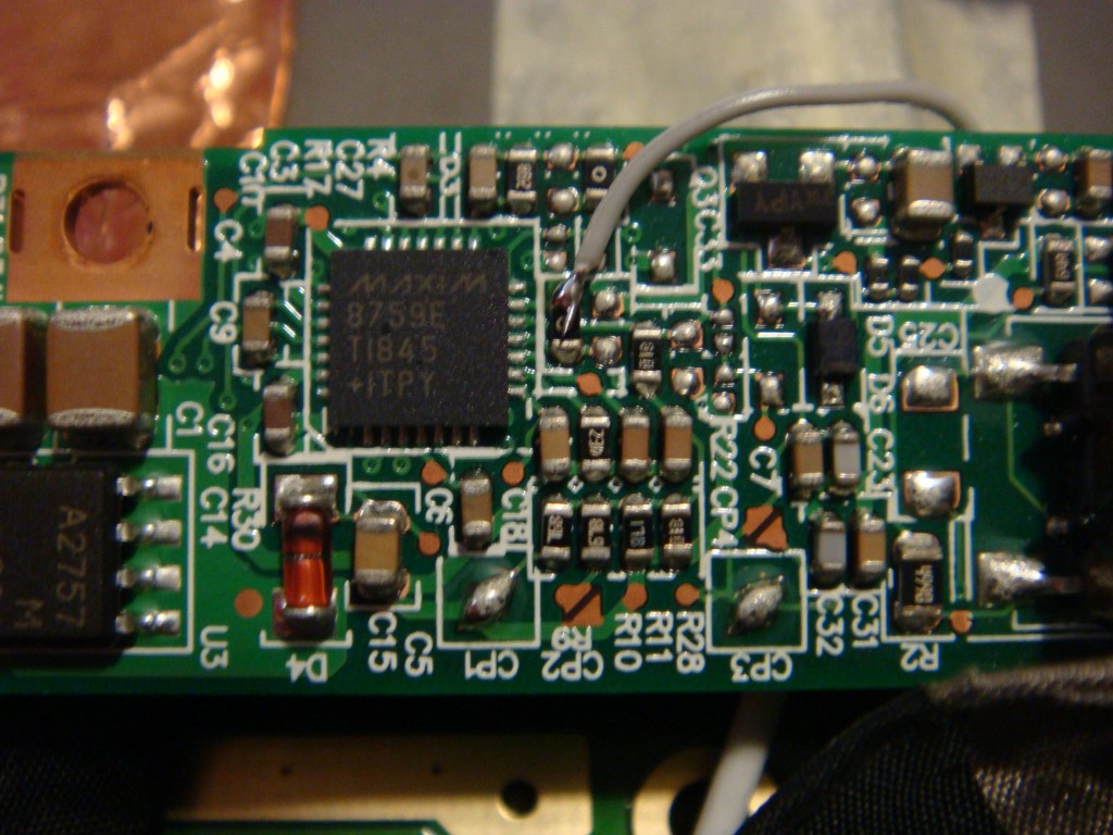
The inverter that drives the fluorescent lamps in my display is based on a MAX8759. This chip has an SMBus interface as well as an ambient light sensor interface and a PWM input. The motherboard uses the SMBus interface to control the inverter. You can directly write values to a brightness register, from 0x00 to 0xFF for minimum to maximum brightness. The function keys send incrementally smaller or larger values to the controller. I pulled out my logic analyzer, mbed, and realterm to watch the bus communication and communicate with the inverter controller.
The communication from the EC to the inverter controller is correct, and you can read the brightness register and see the values change based on the function keys. However the brightness continues to stay low. You can also read the fault register, but no faults were present in my case.
What I figured out was the controller by default uses a mode called “SMBus with DPST”, which takes the SMBus brightness value and multiplies it by the PWM duty cycle. This apparently allows another interface to use the PWM input and dim the display without needing to access the bus. The problem was the PWM duty cycle from the EC was 0%, so the controller kept the brightness at 0 regardless of the SMBus setting.
I first tried setting the controller mode to just SMBus by writing to the control register. This worked, and the display immediately brightened up and followed the function key inputs. However the POR condition of the register is to use DPST, and the EC doesn’t write the value to the control register, so it won’t persist through a restart. What I did to fix it was pull the PWM input line to VCC, which is equivalent to a 100% duty cycle. This lets the brightness track the SMBus value at all times.
To do this you can solder a small wire to a resistor next to the chip that is connected to VCC, and solder the other end to the PWMI signal. I found a trace on the backside that is easy to solder to. Remember to cut the trace on the motherboard side of your jumper wire, since you are putting VCC on a line that the EC is driving low. The EC is pretty sensitive so you would permanently damage the EC PWM line. I don’t expect to ever undo this little fix, but if I do I want the PWM line operational.
1 Comment to M17x inverter brightness fix
Leave a Reply
Other Stuff
Recent Posts
- 6CY7 dual triode valve amplifier
- Air quality sensor (TVOC and eqCO2)
- Automotive rear fill “surround sound” with Boss DD-3
- Spring tester / weight scale
- Ducati 749/999 Tail Light
- Instruments for the GSXR
- Light pipe tail light for the GSXR
- M17x 6990m / 6970m overheating
- PAR / Spectrum analyzer
- Acrylic polishing and scratch removal
Archives
- May 2019 (2)
- April 2017 (3)
- October 2015 (1)
- May 2015 (1)
- March 2014 (2)
- December 2013 (1)
- July 2013 (1)
- November 2012 (1)
- October 2012 (4)
- September 2012 (1)
- August 2012 (3)
- June 2012 (1)
- March 2012 (1)
- February 2012 (1)
- January 2012 (1)
- October 2011 (3)
- July 2011 (1)
- June 2011 (3)
- May 2011 (2)
- April 2011 (1)
- December 2010 (1)
- August 2010 (1)
- July 2010 (3)
- April 2010 (2)
- March 2010 (2)
- January 2010 (2)
- December 2009 (2)
- October 2009 (2)
- September 2009 (1)
- August 2009 (15)


Estimado buenos días estuve leyendo la solución que le diste a este inverter , pero me quedo la duda , cuando dices puentear un cable de VCC a PWMI, en que parte aíslas o que pad cortas??.
saludos.