Electronics
Netgear WGR614v7
I’ve reached the conclusion that this wireless router is pretty much useless. Despite my earlier efforts of heatsinking the processor (which did help), sending email logs when the log was full (unsure if that was useful at all), and updating the firmware to the latest and greatest the thing would still refuse to connect to the WAN randomly.
I did some more digging and figured out that the router doesn’t really have a WAN port, despite the port on the back being labeled as such. The switch controller is actually a six-port controller, and only five are used. Even though the WAN port on the router is physically separated from the other four ports, the switch controller sees it exactly the same as the rest. All five of the ethernet ports on the back are auto-sensing ports so any one has uplink capability. The polarity of the connection is tested during link or when more than three packets are received with inverted end-of-packet pulses. If any of the ports exhibit this behavior the switch controller reverses the port polarity and stores that status in a register. That port then becomes an uplink.
What I figured out was that if the switch ports are used for other devices, the router will eventually fail to uplink. That is, if you use it as an access point instead of a router, it’s fine. When you start using the switch ports it gets confused. I have successfully had the router running for a while by connecting my wired devices through a switch and then uplinking just the switch to port 2, with the router then uplinking to the gateway. Evidently the router’s processor has an issue with its mapped memory.
I’ve now bought a Linksys E2500 wireless N router to replace this thing. You can get refurbished wifi routers at Cisco’s store for about half price.
Netgear wireless router repair
My wifi internet connection has been slowly deteriorating. I originally thought it was my trusty old IBM T42 going out, but when I got my Alienware M15x it was still bad with that machine. I’ve had a few problems with this router: it sometimes refuses to allow wireless connections to access the gateway. If you log in to the router’s interface over wifi via it’s IP and clear the log, it will then allow wifi access to the gateway. I set up the router to automatically email the log to an email address when the log is full. That worked for most of the time, but occasionally you still have to log in and do it manually.
Recently though the connection speed over wifi plummeted. I was going to buy a new wireless AP, but I’m pretty cashed at the moment so I took the router apart to see if I could buy some time.
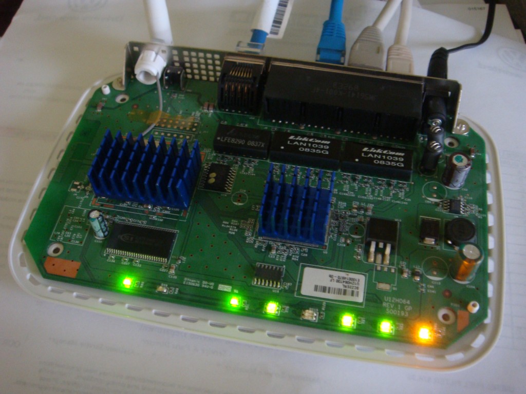
You could pretty clearly see that the microprocessor has overheated. The conformal coating is brown on the bottom side of the PCB. I used an infrared thermometer to measure the temperature of the chip, it was running at about 74°C. The ethernet switch controller IC had a similar temperature, but it’s a larger leaded package whereas the CPU looks like a BGA package. I had some memory heatsinks that I cut to fit the two chips, and with that and some thermal paste I had heatsinks for the two heaters in my router case. They are low profile enough that the case will still go on.
My router works like it should again: speedtest.net reports an average of 18Mbps download speed. The heatsinks keep both ICs at about 49°C now. Guess I won’t need that new AP for a while.
Alienware AlienFX repair
So the other day I was browsing craigslist looking for a way to get rid of one of my Xbox 360s. I found a posting for an Alienware m15x laptop, which said they would be willing to trade for an Xbox. It had an issue where it would shut down if you moved the lid. Since it was otherwise working, had the 1920×1200 LCD, T9500 CPU, 4GB RAM, Blu-ray, etc. I picked it up.
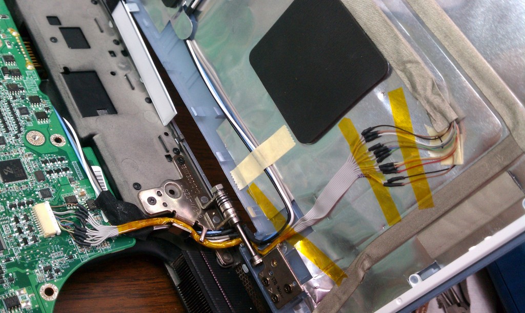
I tore it down and figured out the problem: the wire bundle for the lid’s AlienFX lights was chafed bad where it goes through the hinge. It was shorting out which is why it would shut down. I carefully seperated out the melted wires and repaired the bundle with a fine-gauge hard drive cable.
Canon A70 CCD replacement
I just bought a Canon A70 from eBay for about $20. This camera is pretty dated but it has a surprising set of features for a point and shoot camera. It also runs on AA batteries and not some stupid battery pack that will fail about a year after you buy it. The CCD wasn’t working when I got it though. Since I also picked up one of Canon’s awesome underwater housings for this camera (WP-DC700) I’m into the whole package for about $45. Really though it’s the underwater housing’s coolness that motivated me to fix the camera. Since a bad CCD is a common A70 problem I decided to fix it and found a refurbished CCD on eBay for eight bucks. I made a video of the replacement and embedded it at the end of this post.
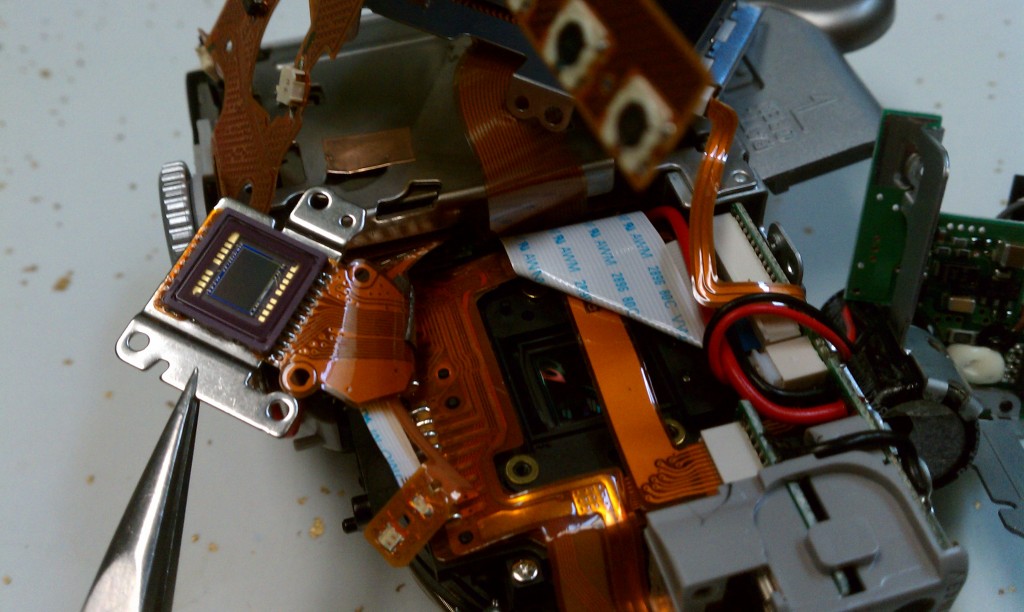
It turns out that the CCD wasn’t what was wrong with my camera though. Canon repaired a slew of these cameras saying that some of the CCDs they sourced were faulty. On my camera the problem was the connector on the mainboard for the CCD, not the CCD itself. The latch that locks in the CCD’s flexible circuit board was incredibly frail. › Continue reading
Flash a monitor’s EDID with an mbed and RealTerm
If you’ve ever setup ATI’s Eyefinity with bezel correction or connected your computer to a TV you know what this is about. Bad EDIDs can be missing supported resolutions, or report an incorrect screen size. In my case bad EDIDs prevented me from enabling bezel correction on my Eyefinity three monitor setup. This is because ATI coded their Catalyst drivers to read the EDID data directly from the monitors instead of the windows registry, where bad data can be fixed more readily with an EDID_OVERRIDE key.
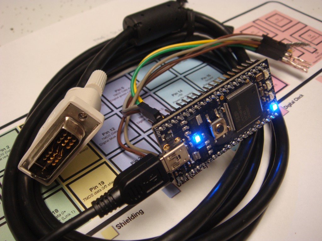
EDID is Extended Display Identification Data. It’s what makes your monitor “Plug and Play”. When you plug a monitor into your computer, the monitor communicates data about itself to the computer over the DDC bus, which is an I2C bus. For a DVI connection, the I2C data and clock lines are on pins 6 & 7. Usually you would flash your monitor’s EDID while it’s hooked up to your PC with a program like Powerstrip, but you have to buy the registered version of powerstrip to have that functionality. Additionally, revision 3 of the EDID specification requires the EDID to be write-protected. That means to flash the EDID with Powerstrip you need to figure out the manufacturer’s sequence for temporarily unlocking the EEPROM. Something like turning the brightness and contrast to zero, then power cycling while holding the menu button, etc. I didn’t feel like messing around with that so I just took the monitor apart. › Continue reading
Pressure mapping with DIY foam load cells
I had an idea a while back to make a pressure sensing pad for testing saddle fit on horses. The intent was to create an array of pressure sensing cells, which could then be used to produce a pressure map that would represent any pinch points on a horse’s back. I found that you can buy this sort of thing, but it’s way too expensive for the average guy. I decided to try and make my own for cheap. I ended up making one from a handful of copper-clad PCBs and 1/4″ shipping foam.
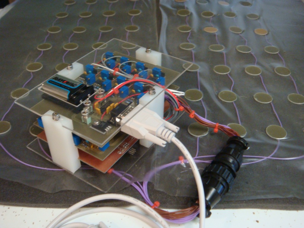
The active area of the pad is approximately 2′ x 2′. I think the foam is polyurethane open-cell foam but I’m not sure. It’s the stuff you use to pack shipping crates. The load cells are made by sandwiching the foam in between 1″ circle cutouts of copper-clad FR4 PC board. I used single sided board and a hole saw with the pilot bit removed (use a drill press and a clamp). The capacitance varies as the foam compresses, and the amount of capacitance is directly related to the thickness and density of the foam, as well as the area of the copper conductors (plates). So you can create any size or thickness load cell you want really. A bigger plate results in more capacitance, as does placing the plates closer together. I estimated the capacitance I would have in my application with this calculator I found at Daycounter engineering services.
I created an array of 64 cells by making 8 rows and 8 columns, each with 8 copper-clad discs. Wherever the row/column discs align a load cell is created. An AVR typically has eight available ADC inputs along with another eight control outputs, so this way you can scan down through the rows and columns to measure each cell. A square wave is sequentially output on the columns, and after some analog proccessing the AVR’s ADC scans each row. The analog voltage present represents the amount of pressure (capacitance) at each site. › Continue reading
SMS remote control
I’ve been expirimenting with cheap GSM cell phones as remote control devices. I wanted to be able to control stuff at my house just by sending a text from my phone. I also wanted to use an AVR since the options are pretty limitless as to what you can control. I started off simple with relay outputs for stuff like the garage door, outside lights, etc. It could also be useful for the AVR to send texts based on events, but I haven’t messed with this yet.
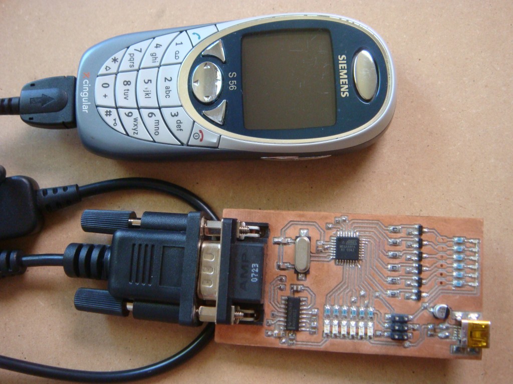
I planned on just having the AVR recognize a particular text string, like “open garage” if I wanted to let someone in my house when I’m not there without giving them a key for example. It’s not overly secure, but you could add a number sequence as a prefix to the command that would be like a password. Then you could periodically change your password if you wanted. › Continue reading
Flatbed scanner panoramic camera
I’ve always loved panoramic pictures, especially when they’re printed up big. I’m not new to panoramics, as I’ve done quite a few stitched sequences, as well as true panoramic film photography. A while back I was wondering if I could repurpose the scanning head part of a scanner into a rotating head panoramic camera. After an initial trial with mediocre results, I did some digging and found out that people have made these before. There’s quite a few issues though: fitting a new lens, an IR filter, the proper speed rotating part, etc. An added difficulty with flatbed scanners is the scanning head scans over a white strip before every scan to calibrate the sensor, so if you don’t have something white for the scan head to look at right at the beginning of the scan, you get some really goofy color stripes. Sheet feed scanners aren’t supposed to do this, so I tried one of those but quickly tired of fooling all of the little switches. It always thinks there’s a paper jam.
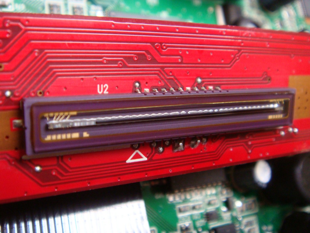
The scan head sensor is actually pretty cool, and by definition it’s a line scan camera. It would still be cool to set it up as a line scan camera to play with.
After seeing this rig at HAD, I’m convinced I’m wasting my time. Moving forward I will be designing a stepper-driven tripod mount for my camera and use stitching software instead. If anybody has any suggestions on good software to try let me know. I’ve been using Panorama Maker or whatever the Nikon bundled program was called. It just doesn’t always do a very good job, even with the special mount I made that’s supposed to eliminate parallax. I get a lot of blurring at the upper and lower edge stitches. I would also like to experiment with multi-row so I can use longer lenses.
Build a 9-digit Pulse Counter for under $20
Recently I was fixing a piece of equipment and wanted a pulse counter to verify a stepper motor system. The existing linear slide was failing, but had a non-standard TPI. The step output was already programmed into a PLC. I had a programmable motor drive, but needed to know how many steps were commanded for a given linear move so I could electronically gear the system to a new linear slide.
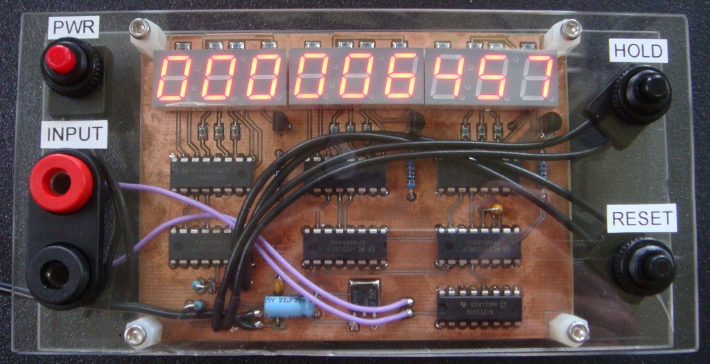
That’s when I found the MC14453 3-digit BCD counter from ON semiconductor. ON semi has integrated three decade counters with an oscillator that multiplexes the 3 digits of an LED display. You pair it with an MC14543 7-segment decoder to have a three segment counter. You can cascade as many of these two chips as necessary by using the overflow output to clock the next stage, and feeding the first scan clock to the next multiplexer. I made a 9-digit counter, but you can do any multiple of three.
I used a MAX232 to drive the input of the counter. It’s a bit of a waste of the MAX232’s abilities, but the MAX232 does a great job of handling a wide range of input signals and it’s only about a buck. The chip can handle inputs from +30V to -30V, and still triggers between .5 and 1.5V with a 5V digital output. It also offers +/-15kV ESD protection on the inputs. With this capability you can sample a variety of different signals without any level shifting (even AC). With a few more input components (current limit resistor, zener clamp, series capacitor) you could capacitively couple the signal and measure anything. I wanted good low frequency performance so I skipped that part.
The parts cost about $6 per 3-digit stage. They are all available at Digi-Key. Part numbers:
MC14453: MC14553BCPGOS-ND
MC14543: MC14543BCPGOS-ND
MAX232: 296-6940-5-ND
7-Seg display: 160-1544-5-ND
The only problem with this arrangement is that the MC14543 is driving the LED segments, so it’s limited to less than 10mA drive current. That makes the segments a bit dimmer than I’d like for easy viewing. If I was doing it again I’d get some cheap transistors to run more current. The display is capable of 20mA.
The schematic can be found in the datasheet for the MC14553. Keep reading for the layout and schematic for my build.
Trailer turn signal update
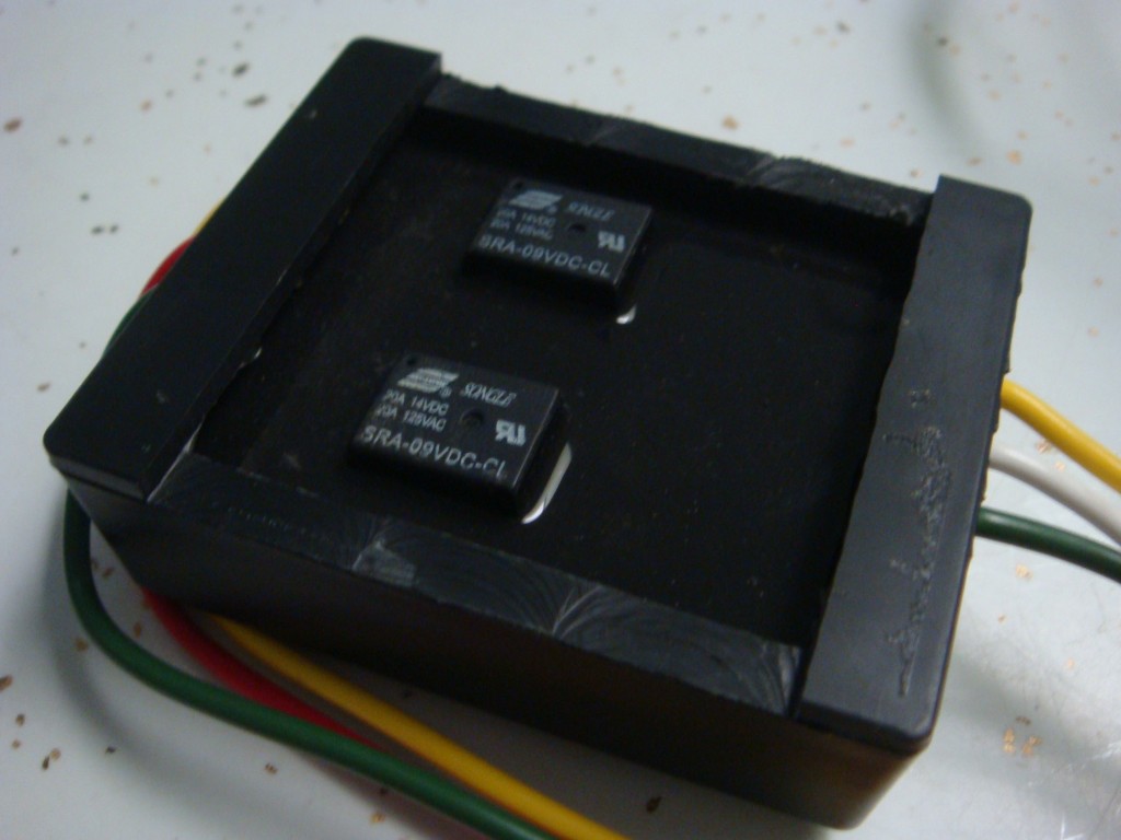
If anyone was interested in my trailer turn signal project, (there was a lot of haters on that one, esp. on Hackaday) Pacman left a comment on that post about an RV turn signal adapter for towing a car at etrailer.com. I bought one of these to try it out. Turns out it does seperate the brake signal from the left and right turn composite signal. So it would work for what I was trying to do. The only thing it doesn’t do that mine did was let the light also act as a clearance light. With my design, the light would be on if the clearance lights were on and flash off to indicate a signal. Not really a big deal though, because you can buy clearance/signal lights to replace the existing clearance lights and use both signals with the same light.
I wasn’t expecting much, but out of curiosity I milled off the top of the plastic box. You can see two relays sticking out of the epoxy potting.
Other Stuff
Recent Posts
Archives
- May 2019 (2)
- April 2017 (3)
- October 2015 (1)
- May 2015 (1)
- March 2014 (2)
- December 2013 (1)
- July 2013 (1)
- November 2012 (1)
- October 2012 (4)
- September 2012 (1)
- August 2012 (3)
- June 2012 (1)
- March 2012 (1)
- February 2012 (1)
- January 2012 (1)
- October 2011 (3)
- July 2011 (1)
- June 2011 (3)
- May 2011 (2)
- April 2011 (1)
- December 2010 (1)
- August 2010 (1)
- July 2010 (3)
- April 2010 (2)
- March 2010 (2)
- January 2010 (2)
- December 2009 (2)
- October 2009 (2)
- September 2009 (1)
- August 2009 (15)