Current sense
330W power supply for M17x update
So everyone that has done the 330W power supply mod that I posted earlier has experienced the power supply shutting down at 240 watts of power draw. That is pretty counterproductive since the M17x ships with a 240W power supply. I did some reverse engineering and some load testing and figured out what the problem is.
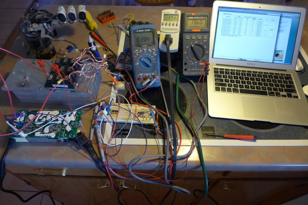
I built a simple dynamic load from a few resistors, two op-amps, and an IGBT that I salvaged from an old motor drive. I attached the schematic at the bottom for anyone that wants to build a similar device. I didn’t have a small enough current sense shunt resistor to handle the current, so I used feedback from the gate-emitter voltage since it is roughly proportional to collector-emitter current after about 10 volts. I also used an MC34072 op-amp since it’s what I had laying around. It’s a bit crude but it works.
The dynamic load let me test the power supply and confirm that it was shutting down at 240W. It did, with the highest power I could get at the output being 19.6V @ 12.5A, roughly 245 watts. I also noticed quite a bit of buzzing.
It is pretty unlikely that Dell would make a power supply that badly, and it successfully powers the M18x so I took a closer look at the only thing that could have any effect on the power supply: the ID wire. When I figured out how to put the 240W 1-wire ID chip in place of the 330W ID chip, I found out that the M17x couldn’t drive the 1-wire bus. Something was loading it down farther down the line. Cutting the ID trace after the 1-wire PROM fixed the issue and allowed the M17x to drive the bus high and charge the PROM so it would work (the PROM is parasitically powered). The only thing that could have an effect was whatever was behind that trace. › Continue reading
Build a spot welder from a battery charger
I ran across a battery charger a while ago that was collecting dust. I looked inside and saw the transformer, heatsinks, high current bridge rectifier and SCR and knew I could do something with it. So I turned it into a spot welder.
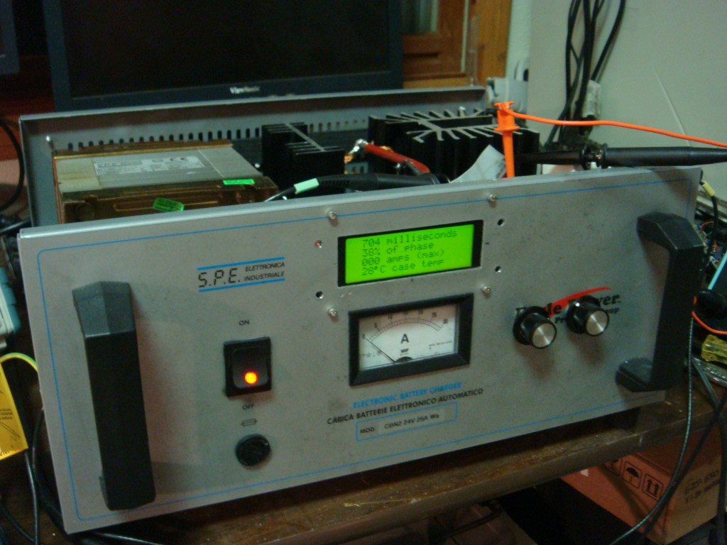
I originally intended this project to weld thin sheetmetal tabs to stuff to act as solder tabs. The project has not been as easy as I originally thought though. (It also suffered some scope creep) It’s my first crack at 5V logic mixed with line AC voltage, and for rolling my own power supply. I used a step-down transformer, bridge regulator and a capacitor to feed an LDO regulator for the control circuit. With the low current draw of the controller, the voltage input to the regulator was relatively free from any ripple thanks to the capacitor.
I ended up frying a processor, LCD, and a couple other components due to a dumb move while troubleshooting the circuit, and overlooking a capacitor’s voltage rating. 120VAC will eat 5V stuff for lunch.
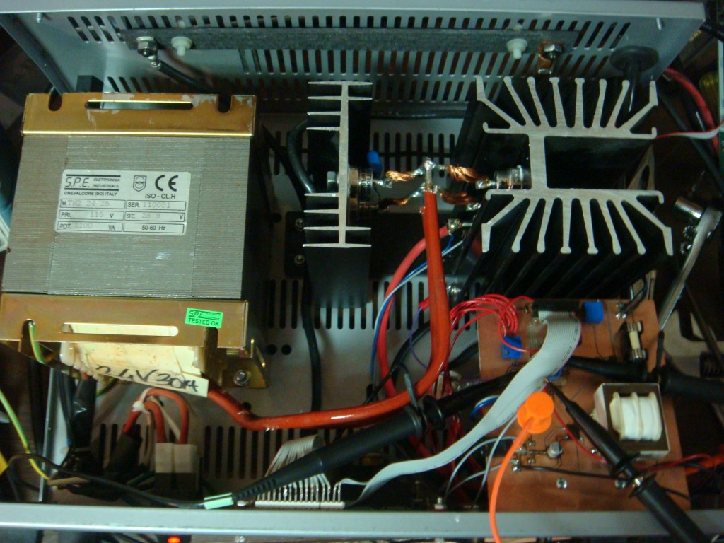
The control circuit basically modulates the SCR, which is hooked up to the output of the bridge rectifier after a step-down transformer. The controller allows for adjustment of duration of the weld and amount of the rectified AC phase that is delivered to the workpiece. The controller holds off the SCR until a pre-determined time of each half phase to control power delivery. An analog comparator detects the zero point of the phase for timing purposes, via a seperate bridge rectifier that has it’s ouput fed through a large resistor to the comparator. A zener clamps the current-limited voltage at 4.8V so as not to damage the micro’s input. A high-to-low transition on the comparator triggers the zero crossing timer. The threshhold voltage is adjustable by an on-board pot.
I also added an Allegro hall effect current sensor that I had lying around from my alternator current sense project. It’s overkill, but it measures the amount of peak current being delivered and displays it on the LCD.
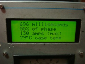
The controller is an ATmega88PA running at 8Mhz. Firmware is written in C with AVRStudio and AVR-GCC. The micro reads the power and duration settings, displays that on the LCD, along with the max current for the last weld cycle and the temperature of the mega’s on-chip sensor. The controller also handles timing duties, zero crossing detection, and control of the SCR gate. The gate is fired by a P-channel MOSFET, with the FET’s gate driven by an NPN BJT on one of the micro’s pins. A footswitch is used as input to the micro to trigger a weld cycle. Both the footswitch input and the zero crossings are buffered by a simple three-sample debouncing routine to prevent erroneous triggers. The system also checks for the footswitch input on power up and after the weld cycle is complete, and waits if the footswitch is down with a message on the LCD to release the footswitch. This allows for safety as well as eliminating any unintended re-triggers at very short durations. Duration is adjustable from roughly one ac cycle to 60 cycles (1 sec). Power control allows from 5% to 95% of each half phase to be delivered to the workpiece.
The SCR’s cathode voltage is available at PORTC2 as a 10:1 voltage divider, and clamped with a zener to prevent damage to the micro. I didn’t need it, so it’s not used in the code.
I’ve also added a power resistor to the output to limit current. I used carbon-carbon as a power resistor (I work in a carbon plant) since it’s free and power resistors are expensive. You only need a few tenths of an ohm to limit the current to a level that won’t destroy the diodes and SCR. I’m overdriving mine at about 130A maximum. It seems to handle it fine for the short bursts. [Edit: 130A isn’t enough though. I may rewire so the diodes/SCR are on the input side and push the current higher by removing or modifying the resistor. Pressure of the electrodes on the joint is also important, still figuring that out.]
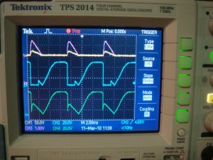
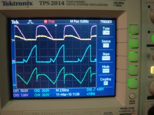
Here’s some drive waveforms: yellow is the output voltage (it’s at 50V/div so it looks small), purple is the output current measured by the hall sensor, blue is the FET’s gate that turns on the SCR, and green is the bridge voltage.
This project has got me thinking about modifying my old “buzzbox” AC welder. I’ve got some big capacitors and IGBTs from a couple old motor drives that could give me a really nice TIG welding power supply. I think I’ve read you can weld high frequency (1-2kHz?) square-wave without needing any HF section. If I remember right square-wave with a positive DC offset is sort of the ultimate TIG welder. Anybody with comments or information about that feel free to drop me a line.
Continue reading for the schematic, PCB layout, and code.
References: Miller Resistance Spot Welding
MAX4173 Current sense amplifier
I just built a current sensing application based on a MAX4173. I am suitably impressed with this device. It is extremely versatile and cheap. The MAX4173 allows you to measure the current across a sense resistor with a 28V common-mode range and provides a ground-referenced output proportional to the current across the resistor. I will probably be using one on most of my projects from now on since I do a lot of prototype work and having a cheap and easy way to sense current draw is pretty useful.
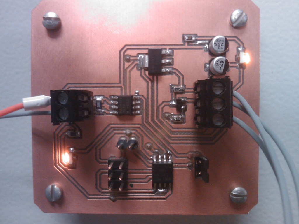
The MAX4173 is available in either an SOT23 or SO8 package, and only requires a decoupling capacitor and a sense resistor to operate. There are three different preset gains available so by combining that with the sense resistor value you can achieve a variety of current ranges.
I used the device in a 4-20mA control loop, with a 20X gain and a 10Ω resistor for a 0.8-4V output into an ATtiny 13’s ADC with a 5V reference. The 10Ω sense resistor is small enough that the loop won’t be affected and large enough to provide good signal range and sensitivity.
For future projects I will probably be using the higher gain version with a smaller sense resistor on the input power line and just leave the MAX4173 output on a header for diagnostic measurement if I don’t have a spare ADC pin. This will limit circuit loading but provide an output for measuring actual circuit current draw.
There is another similar version of the MAX4173, the MAX4080. It can handle higher common-mode voltages and bidirectional current. It’s also a bit more accurate than the 4173, but I haven’t tried it out yet.
How much electric current does a truck really use?
So, a while back my truck was getting slow to start. I checked the battery voltage with the truck running, and it was only 11 volts or something. I started the troubleshooting process by replacing the alternator with one from the local parts store, but it didn’t fix the problem. I changed both batteries. Still didn’t fix the problem. So I did some diagnostics with an ammeter and a voltmeter and figured out that my brand-new alternator was bad. I took it back to the parts store, where they gave me another one. I had them test it, and it failed on their bench tester. So did the next one. They finally gave me my money back and I bought one from Ford. It worked just fine.
While I was looking for alternators, I found some high output models. This sounds cool, but do you really need it? I pull a trailer pretty regularly, and I imagined that the trailer lights and brakes would be a pretty good additional load on the electrical system. I had also read that people buying these “high output” alternators had been disappointed with their actual output, so I thought it might be good to find out.
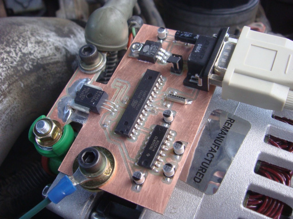
I wasn’t sure how dirty the output of the alternator would be, or how quickly the output might fluctuate which ruled out the use of an inductive current clamp. So I looked around and found a hall-effect current sensor from Allegro Microsystems. The manufacturer’s part number is ACS758KCB-150B-PFF-T. This sensor has a maximum current rating of 150 Amps, and outputs a linear 0-5V signal proportional to the current that passes through the device. It’s fast enough to record transients and will faithfully reproduce both AC and DC currents. The output of the sensor was fed to an Atmel ATMega8, which did ADC duties and sent the data out it’s UART to a MAX232 level converter. I just picked up the data stream with hyperterminal on my laptop. Excel let me manipulate the raw data and make some pretty graphs. I made the circuit with my CNC machine. Here’s what it looks like.
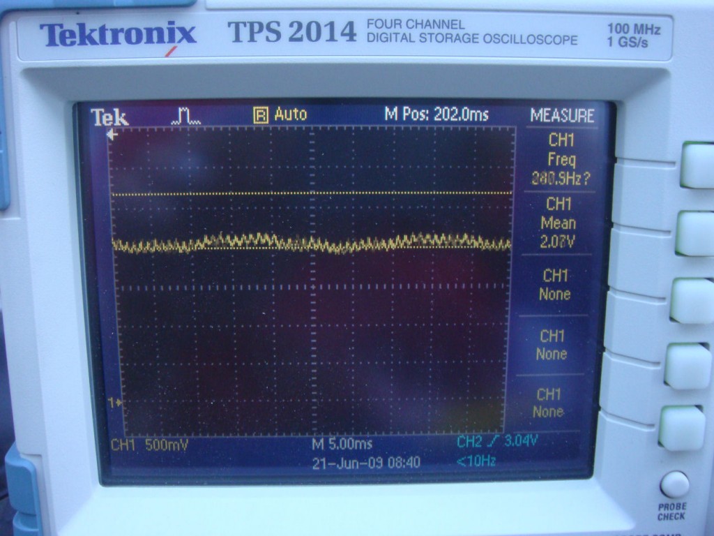
The output of the alternator was alot cleaner than I had expected. I thought there would be more of a rectified three phase look due to the phases generated inside the alternator. This picture of the scope shows the trace of the output of the sensor at idle.
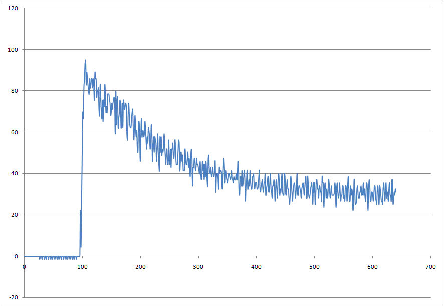
Here is a graph of the data from an engine start up. The Y-axis values are actual current draw in Amps. Time is shown on the X-axis, but the numbers represent the conversion events of the ADC, which happen at approximately 15Hz. This equates to about 40 seconds. The noise is real as far as I can tell. I didn’t use a ground plane, but the trace from the sensor output to the Mega’s ADC input is only about a quarter of an inch. I added a large filter capacitor to the sensor’s output and the waveform didn’t change at all. *edit: I messed that up though, I wasn’t paying attention to where I put it.*
Then I took the truck for about a ten minute drive. I had the lights on, but not the radio or anything extra.
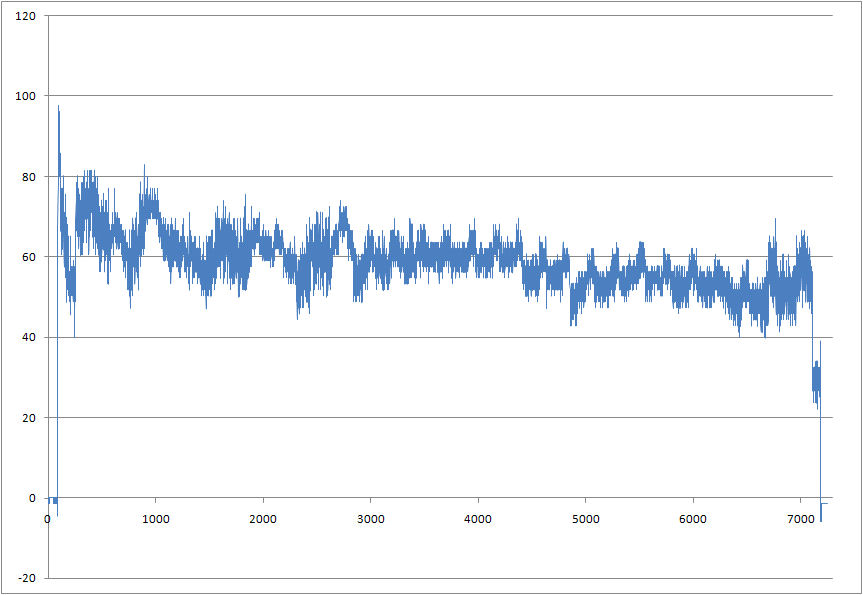
It’s interesting to note how much power the transmission consumes when it’s in gear. The first plot is idling in park, the second plot again shows the truck idling in park at the end of the plot. It’s a clear 20 Amp drop from when the truck was in drive.
I hooked up my horse trailer, but even with all the lights on and everything it only shifted the curve up 10 Amps. The trailer brakes (which I thought would be a significant load) didn’t even show up. I’m still curious about this, as the trailer brake control wiring is usually about 10-12 guage, which is almost the same gauge wire the alternator output has to connect it to the battery. Why bother to wire trailer brake wiring with wire that has an ampacity of 100 Amps or so if it only uses a few amps? There must be more to the story.
Here is the schematic. Sorry it’s not all labelled but I didn’t expect to be posting it at the time. Click on the image to view full size. Capacitors C1 and C2 are for the crystal, 22pF. Capacitors C3-C10 are decoupling capacitors or buffers for the power supply. C11-C14 are typically 1uF. Check the component datasheets for your application.
** I keep getting requests for values, so here is some more detail. The oscillator value is not important, I probably used 8MHz. This circuit doesn’t need high speed. C3 and C4 are decoupling capacitors, usually 0.1uF. C5 and C6 are not necessary, I just added them for flexibility since it was a prototype board. All you need there is C15 which is a bulk capacitor for the voltage regulator. I can’t remember what C7 is, it’s in the AVR datasheet. C9 and C10 aren’t necessary, I was trying to implement a low pass filter but it’s incorrect. All C9 and C10 will do is cause the sensor to drive the output harder. I needed an RC filter but only got the C. That should cover it.
And here’s the layout.
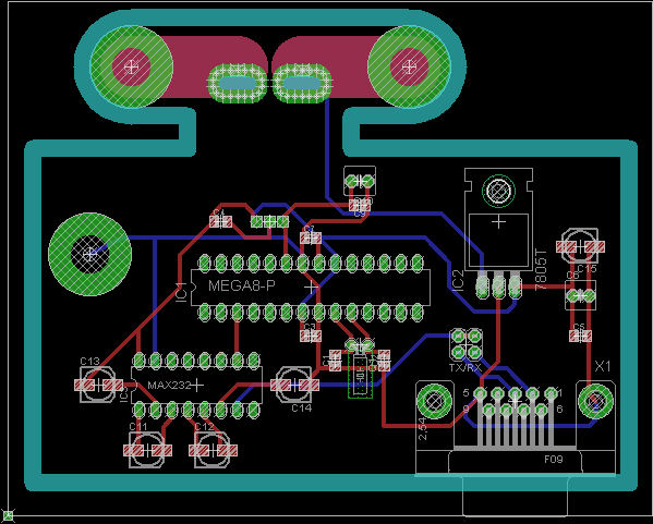
I neglected to add a header for ISP. I was in a hurry to get it done and forgot. The target supply voltage in this application is 11-14V, but supply voltage could be extended to +45V with the appropriate version of the 7805.
Here’s the source code for the Mega8. Compiles with AVR Studio and AVR GCC. It’s a timer-driven interrupt, that starts an ADC conversion of the sensor output and then sends the result to the UART. It uses standard 9600 8N1. The result is left-adjusted so it’s only 8 bit. If you don’t need both positive and negative current measurements, then it would be best to remove the offset of the sensor and use the internal 2.5V ADC reference for better accuracy. The decimal to BCD routine at the end is something I figured out so I can just do a file capture in hyperterminal and import it directly into Excel. › Continue reading
Other Stuff
Recent Posts
Archives
- May 2019 (2)
- April 2017 (3)
- October 2015 (1)
- May 2015 (1)
- March 2014 (2)
- December 2013 (1)
- July 2013 (1)
- November 2012 (1)
- October 2012 (4)
- September 2012 (1)
- August 2012 (3)
- June 2012 (1)
- March 2012 (1)
- February 2012 (1)
- January 2012 (1)
- October 2011 (3)
- July 2011 (1)
- June 2011 (3)
- May 2011 (2)
- April 2011 (1)
- December 2010 (1)
- August 2010 (1)
- July 2010 (3)
- April 2010 (2)
- March 2010 (2)
- January 2010 (2)
- December 2009 (2)
- October 2009 (2)
- September 2009 (1)
- August 2009 (15)
