Alienware
M17x 6990m / 6970m overheating
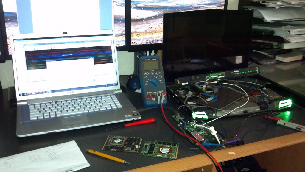
How to fix AMD 6900 series cards overheating in the Alienware M17x. › Continue reading
330W power supply for M17x update
So everyone that has done the 330W power supply mod that I posted earlier has experienced the power supply shutting down at 240 watts of power draw. That is pretty counterproductive since the M17x ships with a 240W power supply. I did some reverse engineering and some load testing and figured out what the problem is.
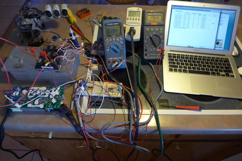
I built a simple dynamic load from a few resistors, two op-amps, and an IGBT that I salvaged from an old motor drive. I attached the schematic at the bottom for anyone that wants to build a similar device. I didn’t have a small enough current sense shunt resistor to handle the current, so I used feedback from the gate-emitter voltage since it is roughly proportional to collector-emitter current after about 10 volts. I also used an MC34072 op-amp since it’s what I had laying around. It’s a bit crude but it works.
The dynamic load let me test the power supply and confirm that it was shutting down at 240W. It did, with the highest power I could get at the output being 19.6V @ 12.5A, roughly 245 watts. I also noticed quite a bit of buzzing.
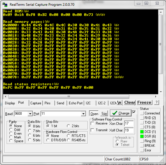
It is pretty unlikely that Dell would make a power supply that badly, and it successfully powers the M18x so I took a closer look at the only thing that could have any effect on the power supply: the ID wire. When I figured out how to put the 240W 1-wire ID chip in place of the 330W ID chip, I found out that the M17x couldn’t drive the 1-wire bus. Something was loading it down farther down the line. Cutting the ID trace after the 1-wire PROM fixed the issue and allowed the M17x to drive the bus high and charge the PROM so it would work (the PROM is parasitically powered). The only thing that could have an effect was whatever was behind that trace. › Continue reading
330 Watt power supply for Alienware M17x
I successfully managed to modify the M18x 330W power supply to work in the M17x, which allows for running the M17x with a fast processor and SLI / crossfire. [Update: some people are having issues with the 330W PS running a 920XM processor with 7970m CrossfireX. This combination draws more than than 330W in the M17xR2 for some reason. I have an 840QM and 6990m CrossfireX with no issues, about 200W average] The modification is easier if you already have a 240W power supply, since you will already have the DS2502 1-wire EPROM that is required for the mod. If you don’t have a 240W supply you can also order a DS2502 and program it manually with the 1-wire programmer I posted here. › Continue reading
mbed 1-wire EPROM driver (DS2502)
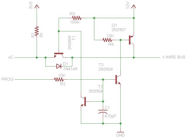
I wrote some code for my mbed to read and program the memory contents of 1-wire EPROMs like the DS2502. It should work with any device that responds to the same commands. The code can read ROM, status registers and memory pages, and write to the status register and memory pages. I also incorporated support for cyclical redundancy checks since the devices aren’t erasable. I had to build an external circuit for the 12 volt programming pulse to protect the mbed signal pin. If you only need to read you don’t need this, but it is required if you want to program data. Download link to the project source files is below.
M17x inverter brightness fix
After I killed my original motherboard modifying stuff in my 6970m quest, the brightness of my LCD was stuck at low with both the new R1 and R2 motherboards. The function keys couldn’t adjust brightness and neither could windows. Here’s how I fixed it. This is probably only valid for a CCFL backlit display.
The inverter that drives the fluorescent lamps in my display is based on a MAX8759. This chip has an SMBus interface as well as an ambient light sensor interface and a PWM input. The motherboard uses the SMBus interface to control the inverter. You can directly write values to a brightness register, from 0x00 to 0xFF for minimum to maximum brightness. The function keys send incrementally smaller or larger values to the controller. I pulled out my logic analyzer, mbed, and realterm to watch the bus communication and communicate with the inverter controller.
The communication from the EC to the inverter controller is correct, and you can read the brightness register and see the values change based on the function keys. However the brightness continues to stay low. You can also read the fault register, but no faults were present in my case.
What I figured out was the controller by default uses a mode called “SMBus with DPST”, which takes the SMBus brightness value and multiplies it by the PWM duty cycle. This apparently allows another interface to use the PWM input and dim the display without needing to access the bus. The problem was the PWM duty cycle from the EC was 0%, so the controller kept the brightness at 0 regardless of the SMBus setting. › Continue reading
6970m power issues
I was recently working on getting an AMD 6970m working in an R1 M17x. I didn’t get it working, but that’s probably largely due to the fact that I was testing with a bad card.
When the computer powers on, before it POSTs, it applies voltage to the three power rails for the graphics card. The graphics card is supposed to turn on its regulators and when things stabilize assert the MXM power_good signal. This happens before any signals are applied to the card’s busses. However if one of the regulators is out of spec, the power_good signal remains low and the computer will not even start POST so you won’t get any error codes, just a black screen.
I looked up the datasheets for the card’s two main regulators and measured the voltages produced. The regulator that I think probably runs the memory chips (APL5913) was spot-on but the regulator for the core (ISL6228) was off by about a tenth of a volt. Hence the failure to release power_good and continue boot. › Continue reading
Upgrade M17x R1 to R2 motherboard
I have an Alienware M17x that has the Core 2 Quad processor. This isn’t a bad setup, but an i7 in the R2 is much better. There is also the restriction that the R1 can only run the GTX 260m, 280m or AMD 5870m. This makes the M17x mostly obsolete for any modern games. I tried quite a few things to get an AMD 6970m running in the R1 (see here), including modifying the MXM structure in the BIOS. I wasn’t successful, mostly because I eventually figured out that the card I got off eBay to test with was bad. However, I did figure out that an R2 motherboard can replace the R1 motherboard. You will of course need a new processor and the CPU/southbridge is in a different location so you also need an R2 heatsink. Everything else is compatible, and the R2 will run the 6970m.
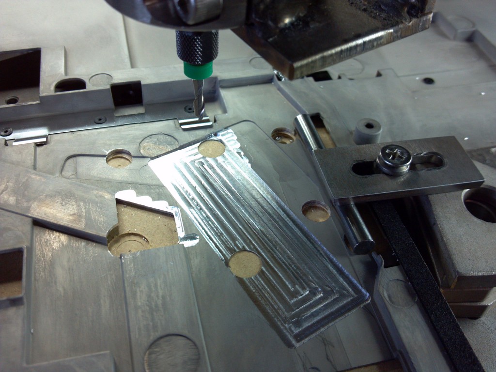
The only things I had to modify was the LVDS link width for the R1 LCD and the magnesium plate that covers the motherboard. Since the heatsink is in a different location you need to relieve a couple spots.
For the LVDS connection the BIOS for the R2 specifies a 24-bit width and the R1 is an 18-bit width. I modified the MXM system info in the BIOS to fix that and updated the checksum. Then I flashed it to the motherboard. I did this before I figured out the 6970m was dead, so I don’t know if the R1 LCD will work or not without running a modified BIOS since it never POSTed and I fixed the card after flashing the BIOS. › Continue reading
6970m vBIOS ISP / Pm25LD010
My latest project is trying to get an AMD 6970m graphics card working in my first release Alienware M17x. I needed a way to program the flash memory on the card that holds the BIOS, since the system won’t post with the card installed. The flash is a Pm25LD010 which is a 1Mb SPI 3.3V flash chip. I had the programmer I built for the last project with the M17x motherboard BIOS issue, but the SST25VF016B it was programmed for has a different program/erase operation. It’s also a bigger flash.
I modified the code for programming the SST25VF016B so that it works with the Pm25LD010 in the same programmer. If you build the programmer from my previous post this code will program the flash on the 6970m.
The code is C for linux. Just make from the directory, or the zip file here also has a compiled executable.
Alienware M17x BIOS / EC corrupted flash fix
I recently bricked my M17x trying to update the EC firmware for the PS2 scan rate fix. I created a USB Crisis rescue disk from the Dell package and booted from it. The Phoenix Phlash utility then informed me that it couldn’t flash when memory managers were present, and that I could press any key to exit. So I pressed a key. Instead of exiting however the program started trying to program the BIOS flash. It quickly locked up, and after I cycled power I got no response at all from the computer.
I found out once I tore down the machine that I had an original Dell (a.k.a. R1) motherboard. The incomplete BIOS load for the R2 completely confused it, as the embedded controller wasn’t recognizing the power button or keyboard for Crisis rescue (FN+B). It wouldn’t do anything at all. Time to find the flash memory that stores the configuration information.
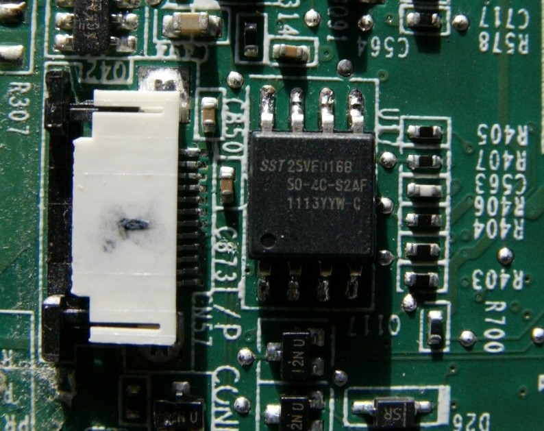
A little examination revealed that the low level functions on this motherboard are managed by an ITE IT8512E embedded controller. This device controls typical BIOS functions like ACPI, fan PWM, keyboard controller/scanner, PS2 input from the touchpad, etc. The controller consists of two domains, the host processor (BIOS) and an 8032 microcontroller (EC). It is not entirely clear from the datasheet how the two domains are integrated; I’m not sure if it’s a logical separation or if there is actually two processors on the device. At any rate the two domains share a common internal flash memory that is mapped from the external flash ROM. On my board this external memory was an SST 25VF016B which is an SPI flash. › Continue reading
Alienware AlienFX repair
So the other day I was browsing craigslist looking for a way to get rid of one of my Xbox 360s. I found a posting for an Alienware m15x laptop, which said they would be willing to trade for an Xbox. It had an issue where it would shut down if you moved the lid. Since it was otherwise working, had the 1920×1200 LCD, T9500 CPU, 4GB RAM, Blu-ray, etc. I picked it up.
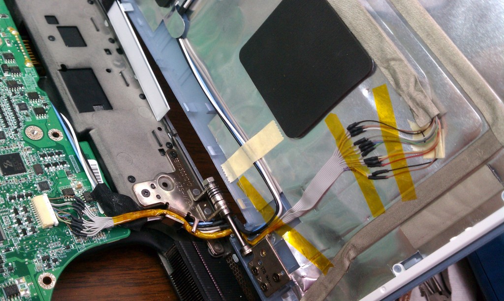
I tore it down and figured out the problem: the wire bundle for the lid’s AlienFX lights was chafed bad where it goes through the hinge. It was shorting out which is why it would shut down. I carefully seperated out the melted wires and repaired the bundle with a fine-gauge hard drive cable.
Other Stuff
Recent Posts
Archives
- May 2019 (2)
- April 2017 (3)
- October 2015 (1)
- May 2015 (1)
- March 2014 (2)
- December 2013 (1)
- July 2013 (1)
- November 2012 (1)
- October 2012 (4)
- September 2012 (1)
- August 2012 (3)
- June 2012 (1)
- March 2012 (1)
- February 2012 (1)
- January 2012 (1)
- October 2011 (3)
- July 2011 (1)
- June 2011 (3)
- May 2011 (2)
- April 2011 (1)
- December 2010 (1)
- August 2010 (1)
- July 2010 (3)
- April 2010 (2)
- March 2010 (2)
- January 2010 (2)
- December 2009 (2)
- October 2009 (2)
- September 2009 (1)
- August 2009 (15)
