Archive for August, 2009
MEMS Accelerometers
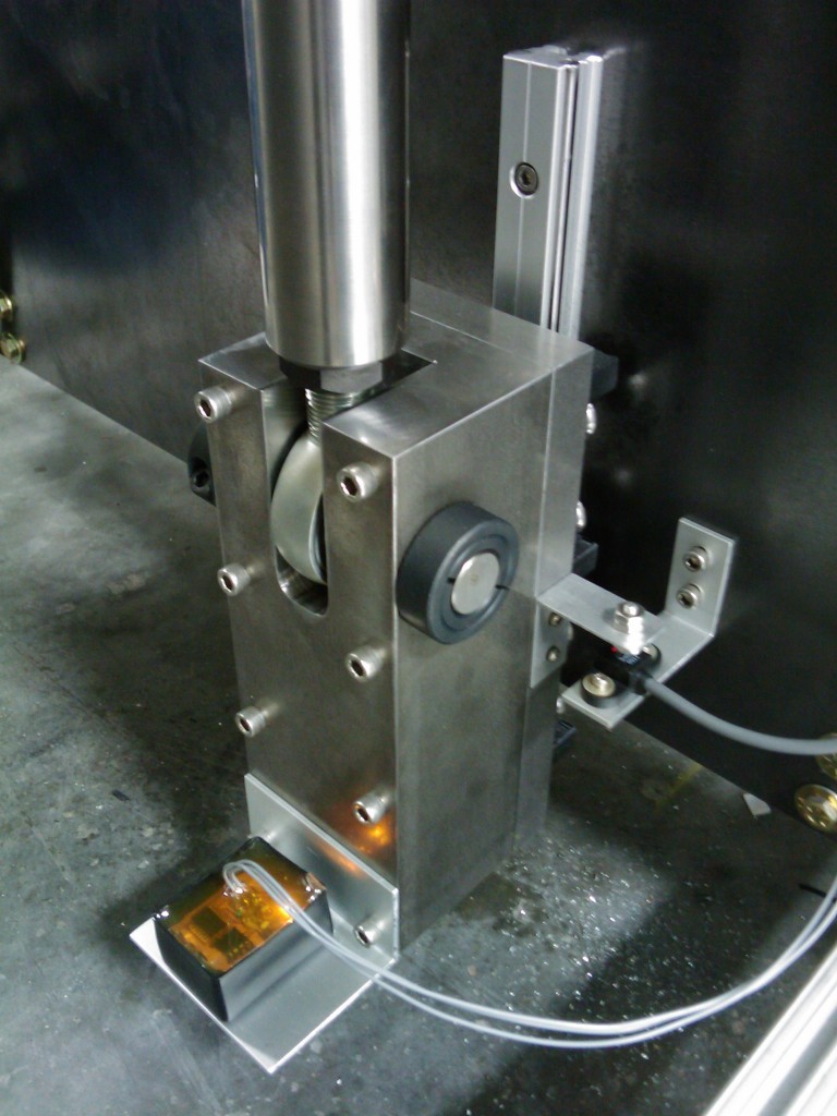
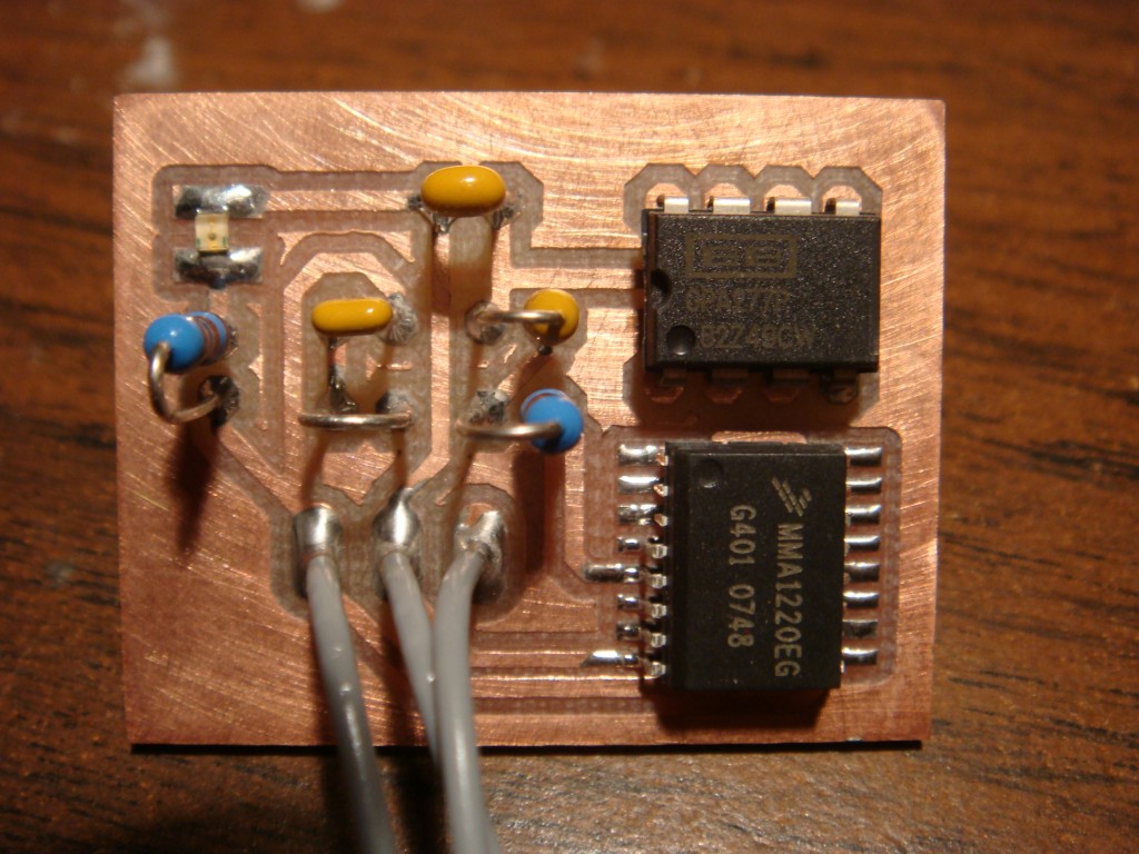
I recently messed with some accelerometers in order to cancel out dead weight in a load cell application. These MEMS (microelectromechanical systems) devices are really handy. They are incredibly small, they have very modest power requirements, and are typically in a standard IC package. The device that I ended up using was a Freescale MMA1220EG. It offers an on-board amplified output and only requires three external components. It uses 5VDC at 5mA, and has a +/- 8g range. The 0g offset is 2.5V and moves from that point at 250mV/g.
I built a simple PCB that mounted the accelerometer and a filter along with an op-amp as a buffer to drive the output and send it down a run of wire. It worked so well I’ve been trying to think up something else to put one on.
Modifying a digital camera for infrared (IR) photography
I modified an older Nikon digital camera that was destined for the trash can to take pictures in infrared. The effect is pretty cool, as the sky shows up really dark, clouds really bright, trees turn out white and alot of colors such as shirt patterns just disappear. It’s rather ethereal, and fun to experiment.
The CCD of a digital camera is usually protected by a piece of glass that is coated to reject IR, because the sensitivity of the CCD is high enough to infrared that it would make your everyday pictures look a little funny. Simply removing this piece of glass isn’t enough though, as by removing the filter, the effective distance between the CCD and lens group changes. This will mess up your focus. So you have to either buy a custom-made piece of replacement glass, or find a way to move the CCD closer to the lens group. Actually, on my camera I found a way to move the lens closer to the CCD and still retain autofocus and zoom capability. There are quite a few different cameras that can be modified to do this, and a quick google search will get you started if you don’t already have one in mind.
The only other piece of the puzzle is an IR-pass filter. This is because you still have to block out the visible light to get pictures in just infrared. IR-pass filters will look totally black. You can get filters which are sensitive to different wavelengths of IR, but those can be a little expensive. The cheap method that I found was to use a piece of exposed film. If you have an old film leader that’s been exposed and developed, it will be transparent to IR and mostly block visible light. It’s not perfect, but it sure is cheap and gets you started.
Here’s a few shots in infrared. They’re a bit fuzzy around the edges because my film filter doesn’t lay completely flat against the lens. Need to work on that someday.


In this shot the shirt draped across the back of my truck is actually red and black.

Horizont: a true panoramic camera
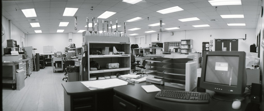
 I have an old Russian panoramic camera that my grandfather gave me called the Horizont. It takes real panoramic pictures, not the cropped variety that drops the little shades in front of the top and bottom edges of the film. It actually scans through something like 120 degrees. The lens rotates on an axis, and the film is wound around the backside of the rotating lens assembly where there is a variable size opening which acts as a shutter. The pictures produced on the film are almost twice as wide as a normal exposure.
I’ve taken quite a few pictures with this camera, but it has a pesky light leak and finding someone that can actually develop and print this film makes shooting with this camera a little tough. Plus it’s heavy. I’ve since moved on to digital stitching software and a special tripod mount for my camera that gives me alot more flexibility. Here are a few of my Horizont adventures though.


Digital RPM indicator
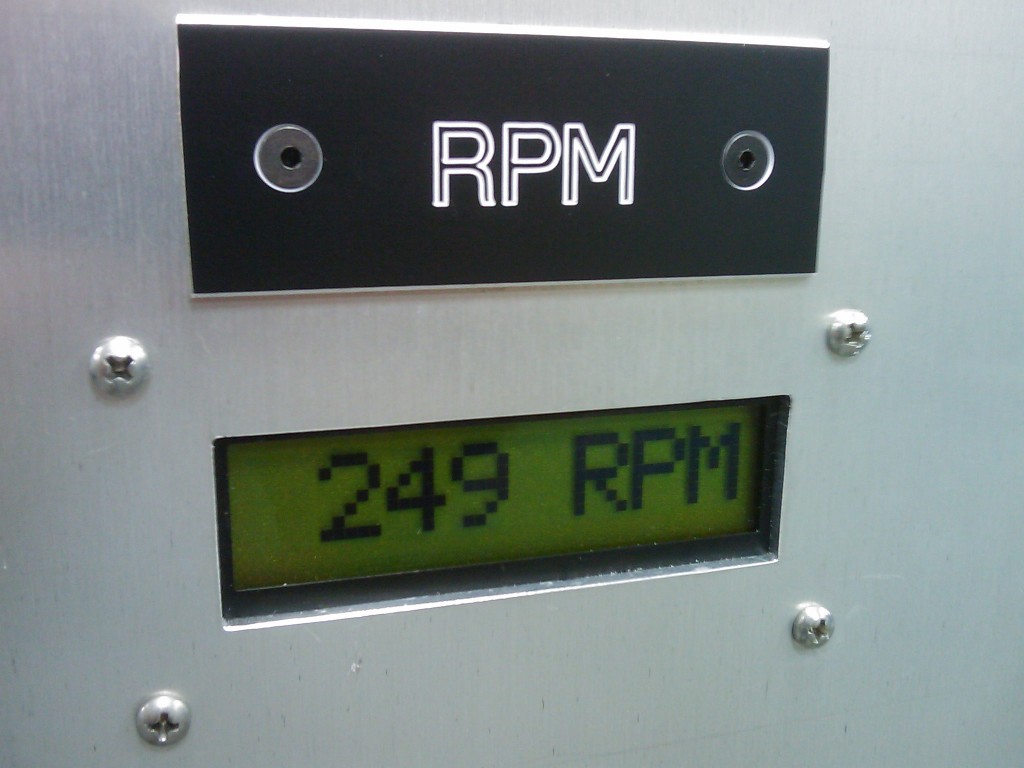
I made a circuit for RPM measurement based on an Atmel ATtiny24 to drive a Hitachi 44780 parallel interface character LCD. It uses an external interrupt request and INT0 to calculate the elapsed time between high/low transitions on the INT0 pin. The elapsed time is then converted to RPM and sent to the LCD. The code will work from RPM values up to 999, and a variable timeout is used for a low cutoff to display 0RPM. The RPM range could be extended to 9,999 or higher by modifying the decimal to BCD routine at the end of the program.
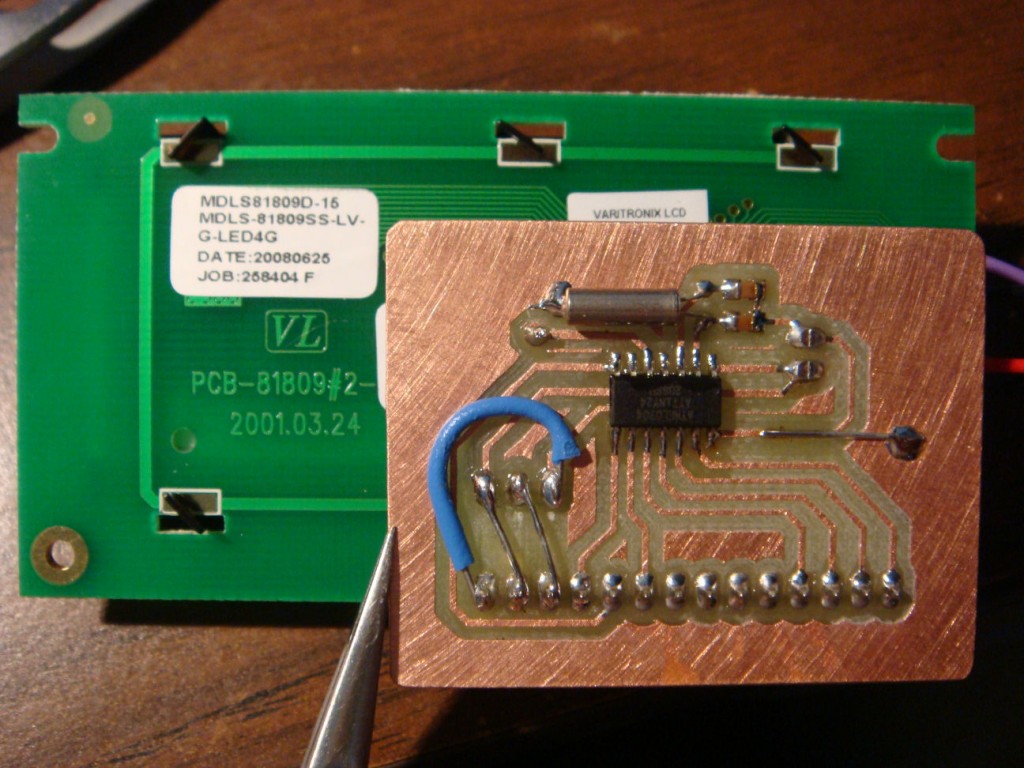
Here is the source code, it compiles with AVR Studio and AVR-GCC. › Continue reading
Training halter fixes pulling back, lunging problems
** Update: I’m sorry but I’m not making these anymore since we’ve taken a temporary break from horses. Thanks! **
I came up with this halter while trying to help a friend get over some problems with her horse. He was fine most of the time, but when she went to take him out to the arena, he would decide it was playtime and do everything short of run over you to get his way. He was regularly pulling the lead rope right out of the hands of his owner so he could escape and run around. It was almost impossible for her to lunge him because he would throw his head to the outside of the circle and make a run for it. She didn’t want a really aggressive halter on him regularly, so I made a dual-purpose halter.
It’s a regular halter, with a hard poly type rope integrated into the nose piece and behind the ears. You can connect the lead rope to the regular halter for comfort, but the lead rope can be easily switched to the second ring and the poly rope will bite in all the right places to get the horse’s attention. It leverages pressure points on both sides of the face and over the poll. This lends it to stopping horses that want to either pull back or pull away. After it was completed we placed it on the young gelding finalizing the fit for pressure points. It worked very well both when he was tied up to stop him from pulling back and also while he was being lunged. If you are interested in purchasing one, send me an email.
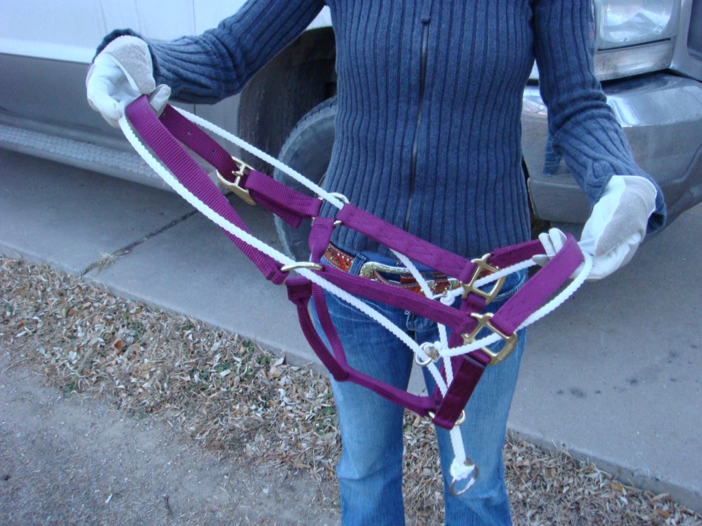
My demo horse Shady

Electronic choke
When I had carbureted vehicles, I always hated the choke spring. They never worked right, no matter how much you twiddled with them. They either never pulled all the way off or never closed enough to start on that really cold day when it’s so much fun to adjust chokes.
I thought the design could use some modernization, so I designed a true electric choke. Or maybe electronic choke is more accurate, because “electric choke” just means a heater mounted to the bi-metallic spring.
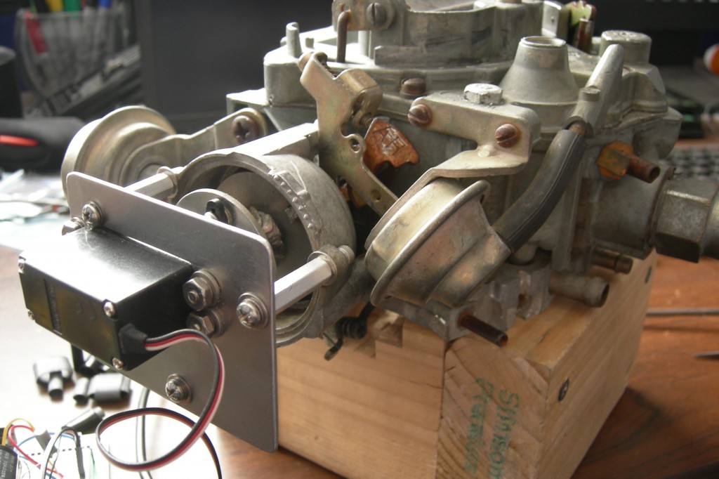
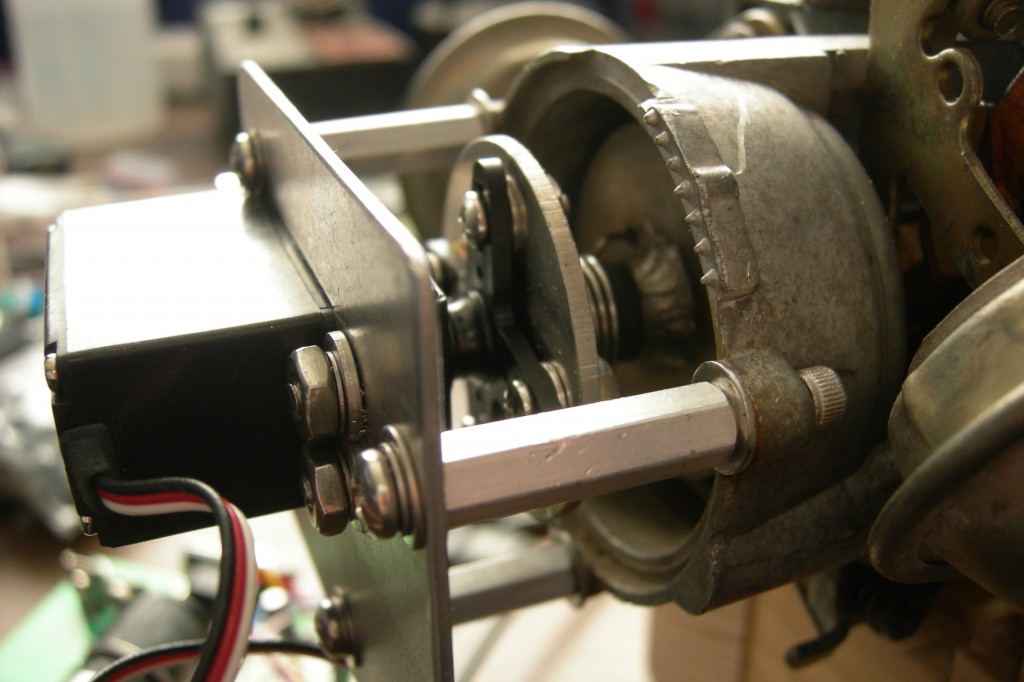
I used a servo to command a certain choke position, and I designed a simple spring mechanism so that the servo wouldn’t burn itself up trying to get to a position when the throttle was closed and the position of the fast idle cam can’t be adjusted. I didn’t have my CNC machine running at the time or I would have made a housing and ordered a smaller servo so that it all had about the same appearance of an electric choke, except for an extra wire. That extra wire would go to a temperature sensor in the coolant circuit.
I would have also added a dip switch for making adjustments to choke pull off points based on engine temperature. If I ever have another carbureted vehicle I might finish it.
My homebuilt CNC machine
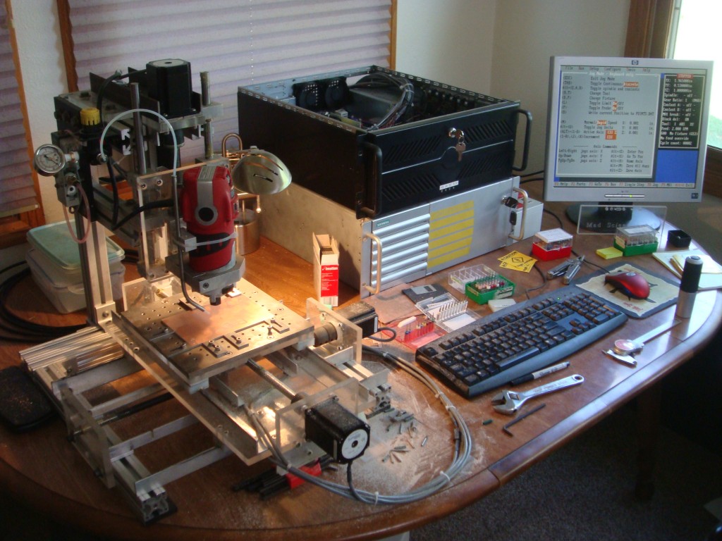
I finally assembled enough surplus parts and scrap material to build a halfway decent CNC machine. I have been looking forward to actually completing this task for some time, but the appropriate parts and materials are prohibitively expensive for the individual on a budget. This spring I managed to complete the project.
Most of the machine is made out of either aluminum or acrylic. These materials are both easy to work with when all you have available is various hand tools and a drill press with a cross slide vise. The motors are NEMA 23 high torque, the threaded rods are 1/2-10 precision ACME and the nuts are anti-backlash. This results in pretty decent X-Y movement. I made the slides from extruded aluminum profiles available at the hardware store and some strips of Teflon.
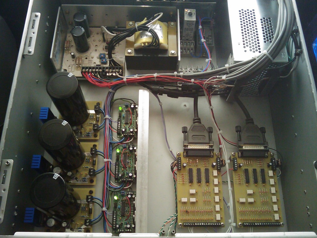
I made all of the electronics that support the machine. I made the optical home and limit switches, as well as both parallel port interface boards. I also assembled the stepper motor drivers and built power filters/regulators for the input to the stepper motor drives on all three axes. This prevents inductive feedback spikes from the motors ruining the stepper motor control ICs. I need this because I’m running the motors at 48VDC and the controller IC has an absolute maximum voltage rating of 60VDC. I also wanted to keep any switching noise and voltage dips from the switch-mode power supply out of the stepper drives. Each filter has a FET-regulated output that clamps the voltage and then sends it out to some big capacitors to prevent the voltage from dropping.
The parallel interface boards completely isolate the controlling PC from the drives and other electronics. Buffers handle all the appropriate levels and opto-isolators keep the ports safe.
I’ve run it extensively with TurboCNC, but I don’t get any of the limit and home functionality because TurboCNC only supports legacy port addresses, and most parallel port PCI cards can’t map to legacy addresses. This leaves me with only the one on-board parallel port, which is mostly used up by the 3 axis step and direction signals. It works in Mach3 CNC, but I can’t afford to buy that program right now. So I’ve used it in evaluation mode for doing simple text engraving on plastics and acrylic. Oddly enough I couldn’t get it to work at all in Mach2. The pulse train output to the stepper drives was inconsistent enough that the motors would stall. I even tried it on a few different computers, one of which was a brand new XP install.
The machine mostly cranks out PC boards thanks to Eagle CAD and PCB2GCode. I’ve made quite a few since the machine was finished. It does a pretty good job, and holds flatness to a couple thousandths. It’s enough to get routine 0.020″ isolation on traces and pads, and clean 0.012″ trace widths. It’s a bit slow because of the low-buck slides, the motors stall if I speed it up much. It’s not exactly a high precision machine, so I can live with slow.
I’ve got some better parts since I built this one, and I’m planning on building another one with much better accuracy in the near future. This machine won’t handle the fine traces necessary to make boards with the newer components.
Here’s a video of the machine in action:
You can see more videos at youtube: imsolidstate’s CNC machine
Fast idle mod
I found this write up by Skweeker at powerstroke.org for adding a fast idle or high idle switch to your pre-’05 6.0l. It takes advantage of the PTO capability that is programmed into the engine computer, even if you don’t have a PTO. Takes only a few minutes, and works great. Note that this write-up is specifically for 2004 with automatic.
“Here’s what you need to do. Look up under the dash between the steering column and the parking brake pedal. You will find a wiring harness behind the parking brake handle with a bunch of wires coming out of the harness that have the ends sealed off with charcoal?? colored heat shrink tubing.
If your not sure what you are looking at, look at the three wiring harnesses that come through the firewall to the left of the steering column shaft into the passenger compartment. The top harness is big, the middle harness is smaller than the top harness and the last harness closest to the floor is smaller still. The wire you are looking for comes out of the the middle harness where the harness routes up to the dash directly behind the parking brake handle.
One of these wires will be Light Blue with a Yellow stripe. This is the PTO function wire from the PCM. Placing battery power (battery positive) on this wire will command the PCM to raise the idle speed to 1200rpm as long as the transmission is in Park or Neutral and the service brake is released, meaning your foot is not on the brake pedal and the brake lights are not activated.
The other wire you are looking for is a White wire with a Light Blue stripe. This one is also easy to find. While looking under the dash direct your attention to the black OBD II datalink connector mounted to the lower part of the dash to the right of the steering column. This connector is what a service tech uses to hook up a scan tool which is needed to communicate with the vehicle PCM in order to check engine sensor data, engine trouble codes and to REFLASH your PCM. (You’ve heard about FLASHES haven’t you???)
Anyway, look at this black connector and follow the wiring harness from the plug back up and inside the dash. Along the harness not too far up from the plug you will find the White wire with a Light Blue stripe included in the bundle of wires but the wire just stops short of the connector. Yes the wire does not plug into any one of the ports of the datalink connector.
This White wire with a Light Blue stipe is your positive battery source wire that you will connect to the Light Blue with a Yellow stripe PTO wire through a switch.”
I installed a rocker switch on the panel just below and to the right of the headlight switch. The plastic is really soft, so it cuts easily with a hobby knife. Plus, the fuse panel drops out right underneath which makes wiring everything up really easy.
Piezo pump
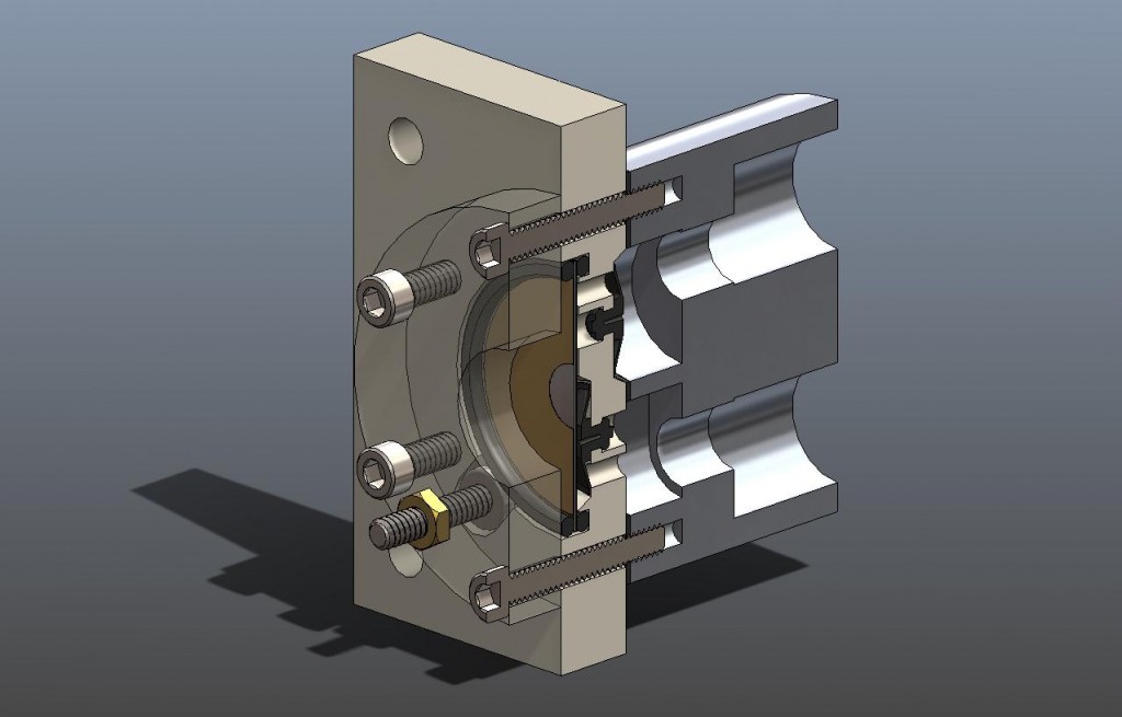
Some time ago I designed a piezo pump to demonstrate a concept for an extremely low flow liquid slurry pumping application. The pump was based around AdaptivEnergy’s Ruggedized Laminated Piezo actuator, or RLP-125. AdaptivEnergy also manufactures the Joule-Thief, which is also based on piezo technology. The actuator was driven by the company’s proprietary electronics that they call the Energy Key. I used umbrella valves from Vernay that allow the pump to build pressure and move fluid.
The pump works very well for extremely low flow liquid and slurry applications. The wetted parts of the actuator are 300 series stainless steel, and the valves and housing can be made of a number of materials for resistance to many fluids. This pump design is a great selection particularly if you are moving an abrasive slurry, as there are less contact wear surfaces like in a more conventional pump.
Perhaps the most interesting thing about this pump is that both the frequency and displacement of the element can be varied. This allows the pump to operate at different resonant frequencies for different fluids, and still accurately control flow.
Here is a 3D section view of the model that I made in Solidworks.
Atmel’s new micro with integrated boost converter
Atmel has announced on their website that they are offering an 8-bit AVR microprocessor with an integrated boost converter that allows operation of the microprocessor’s core all the way down to 0.7 volts. This frees up the requirement for designing an external boost converter to operate on the pico power requirement of at least 1.8 volts.
Obviously, this allows applications to operate on just one typical alkaline or ni-cad cell. Impressive, but I haven’t been able to get my hands on one yet. No suppliers have them in stock, and my sample request has not been acknowledged now for about a month. I have some ideas, so hopefully they will ship some soon.
Check it out at Atmel’s website: ATtiny43U
Other Stuff
Recent Posts
- 6CY7 dual triode valve amplifier
- Air quality sensor (TVOC and eqCO2)
- Automotive rear fill “surround sound” with Boss DD-3
- Spring tester / weight scale
- Ducati 749/999 Tail Light
- Instruments for the GSXR
- Light pipe tail light for the GSXR
- M17x 6990m / 6970m overheating
- PAR / Spectrum analyzer
- Acrylic polishing and scratch removal
Archives
- May 2019 (2)
- April 2017 (3)
- October 2015 (1)
- May 2015 (1)
- March 2014 (2)
- December 2013 (1)
- July 2013 (1)
- November 2012 (1)
- October 2012 (4)
- September 2012 (1)
- August 2012 (3)
- June 2012 (1)
- March 2012 (1)
- February 2012 (1)
- January 2012 (1)
- October 2011 (3)
- July 2011 (1)
- June 2011 (3)
- May 2011 (2)
- April 2011 (1)
- December 2010 (1)
- August 2010 (1)
- July 2010 (3)
- April 2010 (2)
- March 2010 (2)
- January 2010 (2)
- December 2009 (2)
- October 2009 (2)
- September 2009 (1)
- August 2009 (15)