Electronics
Digital RPM indicator
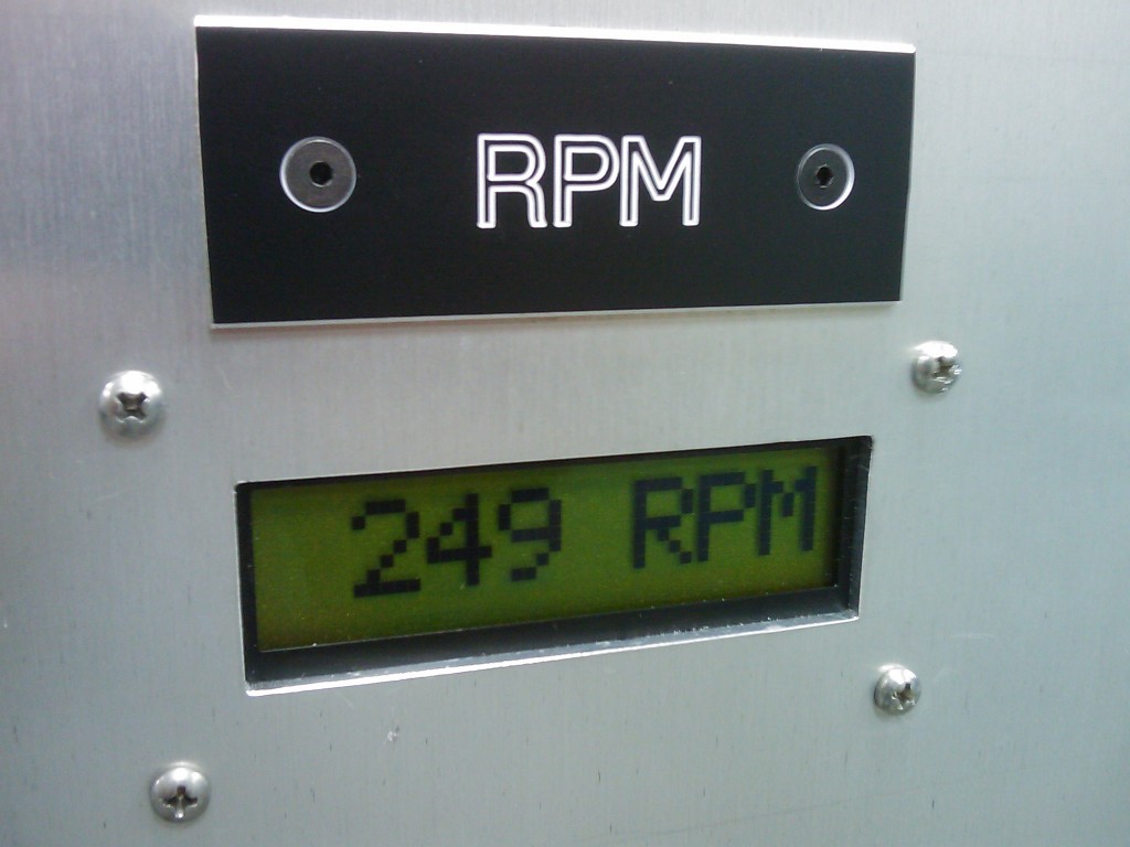
I made a circuit for RPM measurement based on an Atmel ATtiny24 to drive a Hitachi 44780 parallel interface character LCD. It uses an external interrupt request and INT0 to calculate the elapsed time between high/low transitions on the INT0 pin. The elapsed time is then converted to RPM and sent to the LCD. The code will work from RPM values up to 999, and a variable timeout is used for a low cutoff to display 0RPM. The RPM range could be extended to 9,999 or higher by modifying the decimal to BCD routine at the end of the program.
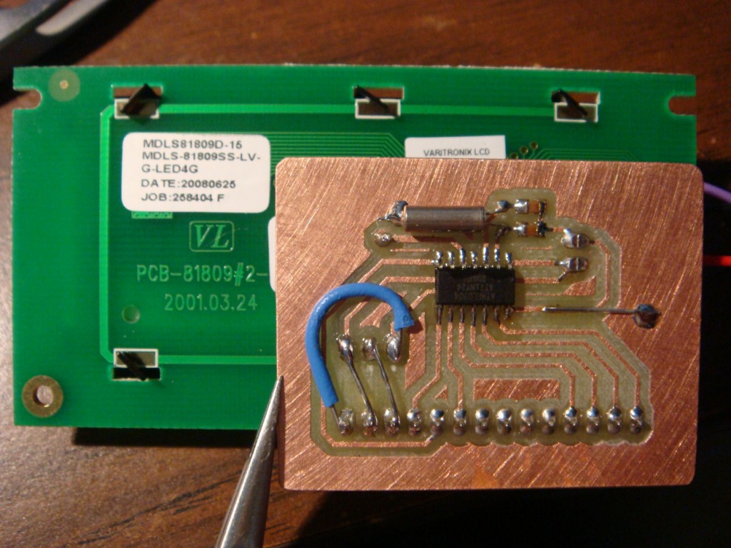
Here is the source code, it compiles with AVR Studio and AVR-GCC. › Continue reading
Electronic choke
When I had carbureted vehicles, I always hated the choke spring. They never worked right, no matter how much you twiddled with them. They either never pulled all the way off or never closed enough to start on that really cold day when it’s so much fun to adjust chokes.
I thought the design could use some modernization, so I designed a true electric choke. Or maybe electronic choke is more accurate, because “electric choke” just means a heater mounted to the bi-metallic spring.
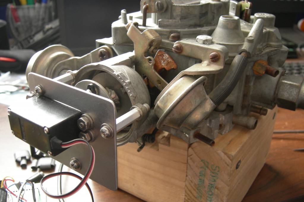
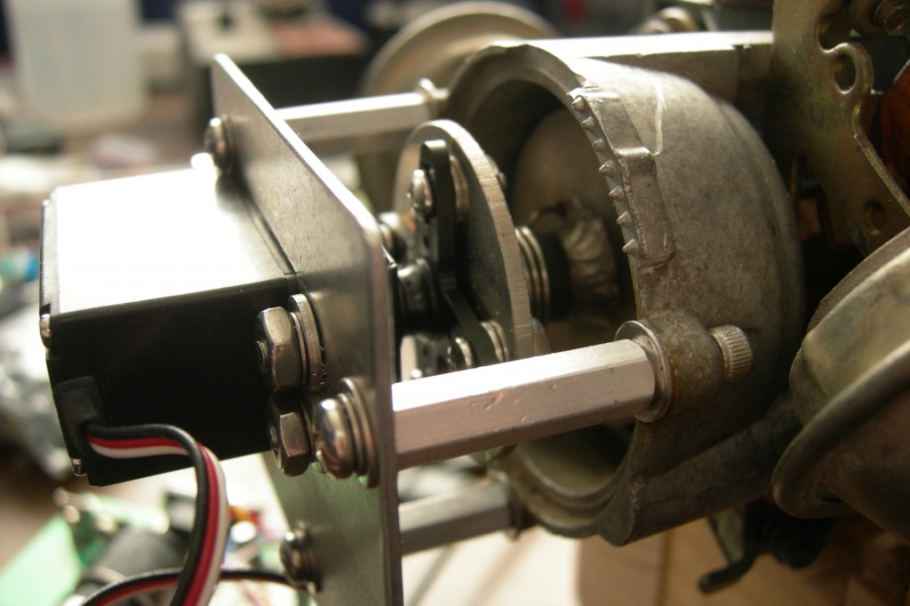
I used a servo to command a certain choke position, and I designed a simple spring mechanism so that the servo wouldn’t burn itself up trying to get to a position when the throttle was closed and the position of the fast idle cam can’t be adjusted. I didn’t have my CNC machine running at the time or I would have made a housing and ordered a smaller servo so that it all had about the same appearance of an electric choke, except for an extra wire. That extra wire would go to a temperature sensor in the coolant circuit.
I would have also added a dip switch for making adjustments to choke pull off points based on engine temperature. If I ever have another carbureted vehicle I might finish it.
Atmel’s new micro with integrated boost converter
Atmel has announced on their website that they are offering an 8-bit AVR microprocessor with an integrated boost converter that allows operation of the microprocessor’s core all the way down to 0.7 volts. This frees up the requirement for designing an external boost converter to operate on the pico power requirement of at least 1.8 volts.
Obviously, this allows applications to operate on just one typical alkaline or ni-cad cell. Impressive, but I haven’t been able to get my hands on one yet. No suppliers have them in stock, and my sample request has not been acknowledged now for about a month. I have some ideas, so hopefully they will ship some soon.
Check it out at Atmel’s website: ATtiny43U
How much electric current does a truck really use?
So, a while back my truck was getting slow to start. I checked the battery voltage with the truck running, and it was only 11 volts or something. I started the troubleshooting process by replacing the alternator with one from the local parts store, but it didn’t fix the problem. I changed both batteries. Still didn’t fix the problem. So I did some diagnostics with an ammeter and a voltmeter and figured out that my brand-new alternator was bad. I took it back to the parts store, where they gave me another one. I had them test it, and it failed on their bench tester. So did the next one. They finally gave me my money back and I bought one from Ford. It worked just fine.
While I was looking for alternators, I found some high output models. This sounds cool, but do you really need it? I pull a trailer pretty regularly, and I imagined that the trailer lights and brakes would be a pretty good additional load on the electrical system. I had also read that people buying these “high output” alternators had been disappointed with their actual output, so I thought it might be good to find out.
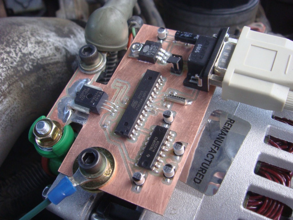
I wasn’t sure how dirty the output of the alternator would be, or how quickly the output might fluctuate which ruled out the use of an inductive current clamp. So I looked around and found a hall-effect current sensor from Allegro Microsystems. The manufacturer’s part number is ACS758KCB-150B-PFF-T. This sensor has a maximum current rating of 150 Amps, and outputs a linear 0-5V signal proportional to the current that passes through the device. It’s fast enough to record transients and will faithfully reproduce both AC and DC currents. The output of the sensor was fed to an Atmel ATMega8, which did ADC duties and sent the data out it’s UART to a MAX232 level converter. I just picked up the data stream with hyperterminal on my laptop. Excel let me manipulate the raw data and make some pretty graphs. I made the circuit with my CNC machine. Here’s what it looks like.
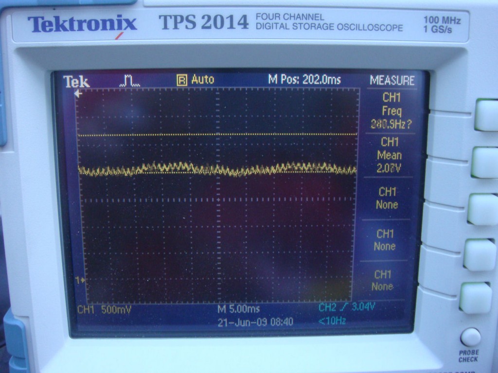
The output of the alternator was alot cleaner than I had expected. I thought there would be more of a rectified three phase look due to the phases generated inside the alternator. This picture of the scope shows the trace of the output of the sensor at idle.
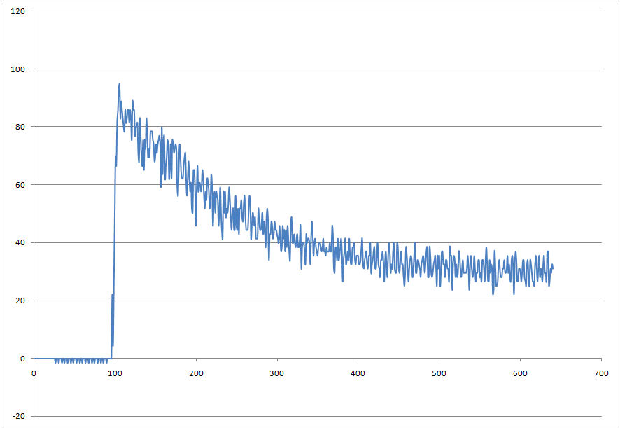
Here is a graph of the data from an engine start up. The Y-axis values are actual current draw in Amps. Time is shown on the X-axis, but the numbers represent the conversion events of the ADC, which happen at approximately 15Hz. This equates to about 40 seconds. The noise is real as far as I can tell. I didn’t use a ground plane, but the trace from the sensor output to the Mega’s ADC input is only about a quarter of an inch. I added a large filter capacitor to the sensor’s output and the waveform didn’t change at all. *edit: I messed that up though, I wasn’t paying attention to where I put it.*
Then I took the truck for about a ten minute drive. I had the lights on, but not the radio or anything extra.
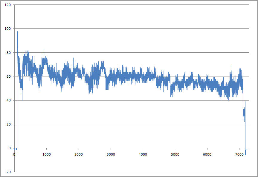
It’s interesting to note how much power the transmission consumes when it’s in gear. The first plot is idling in park, the second plot again shows the truck idling in park at the end of the plot. It’s a clear 20 Amp drop from when the truck was in drive.
I hooked up my horse trailer, but even with all the lights on and everything it only shifted the curve up 10 Amps. The trailer brakes (which I thought would be a significant load) didn’t even show up. I’m still curious about this, as the trailer brake control wiring is usually about 10-12 guage, which is almost the same gauge wire the alternator output has to connect it to the battery. Why bother to wire trailer brake wiring with wire that has an ampacity of 100 Amps or so if it only uses a few amps? There must be more to the story.
Here is the schematic. Sorry it’s not all labelled but I didn’t expect to be posting it at the time. Click on the image to view full size. Capacitors C1 and C2 are for the crystal, 22pF. Capacitors C3-C10 are decoupling capacitors or buffers for the power supply. C11-C14 are typically 1uF. Check the component datasheets for your application.
** I keep getting requests for values, so here is some more detail. The oscillator value is not important, I probably used 8MHz. This circuit doesn’t need high speed. C3 and C4 are decoupling capacitors, usually 0.1uF. C5 and C6 are not necessary, I just added them for flexibility since it was a prototype board. All you need there is C15 which is a bulk capacitor for the voltage regulator. I can’t remember what C7 is, it’s in the AVR datasheet. C9 and C10 aren’t necessary, I was trying to implement a low pass filter but it’s incorrect. All C9 and C10 will do is cause the sensor to drive the output harder. I needed an RC filter but only got the C. That should cover it.
And here’s the layout.
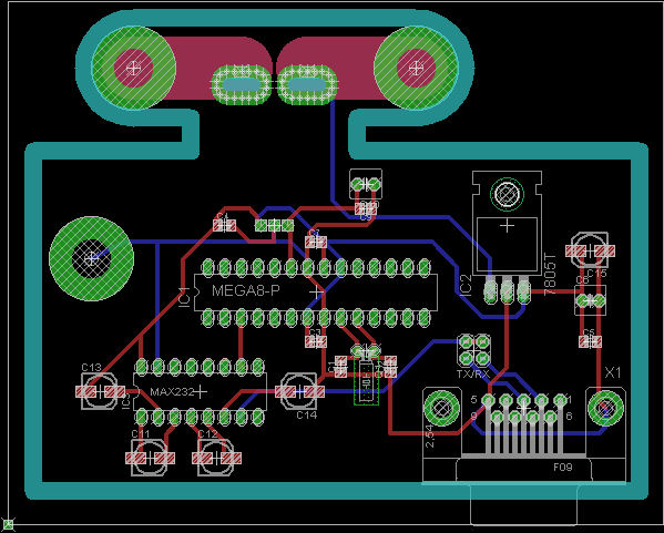
I neglected to add a header for ISP. I was in a hurry to get it done and forgot. The target supply voltage in this application is 11-14V, but supply voltage could be extended to +45V with the appropriate version of the 7805.
Here’s the source code for the Mega8. Compiles with AVR Studio and AVR GCC. It’s a timer-driven interrupt, that starts an ADC conversion of the sensor output and then sends the result to the UART. It uses standard 9600 8N1. The result is left-adjusted so it’s only 8 bit. If you don’t need both positive and negative current measurements, then it would be best to remove the offset of the sensor and use the internal 2.5V ADC reference for better accuracy. The decimal to BCD routine at the end is something I figured out so I can just do a file capture in hyperterminal and import it directly into Excel. › Continue reading
Other Stuff
Recent Posts
- 6CY7 dual triode valve amplifier
- Air quality sensor (TVOC and eqCO2)
- Automotive rear fill “surround sound” with Boss DD-3
- Spring tester / weight scale
- Ducati 749/999 Tail Light
- Instruments for the GSXR
- Light pipe tail light for the GSXR
- M17x 6990m / 6970m overheating
- PAR / Spectrum analyzer
- Acrylic polishing and scratch removal
Archives
- May 2019 (2)
- April 2017 (3)
- October 2015 (1)
- May 2015 (1)
- March 2014 (2)
- December 2013 (1)
- July 2013 (1)
- November 2012 (1)
- October 2012 (4)
- September 2012 (1)
- August 2012 (3)
- June 2012 (1)
- March 2012 (1)
- February 2012 (1)
- January 2012 (1)
- October 2011 (3)
- July 2011 (1)
- June 2011 (3)
- May 2011 (2)
- April 2011 (1)
- December 2010 (1)
- August 2010 (1)
- July 2010 (3)
- April 2010 (2)
- March 2010 (2)
- January 2010 (2)
- December 2009 (2)
- October 2009 (2)
- September 2009 (1)
- August 2009 (15)
