Electronics
PCB layouts and schematics for my CNC
I’ve received some email and comment requests for the layouts and schematics of the electronics running my CNC machine. I’ve pulled together what I can find for this article.
Power Filter Boards
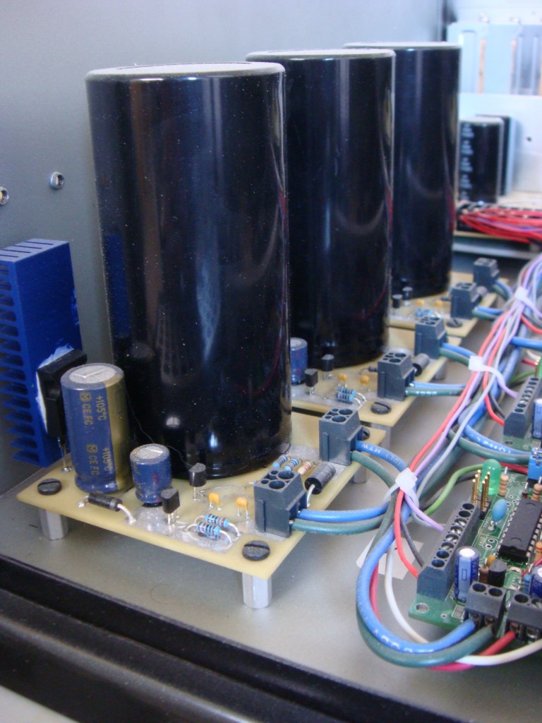
I made these power filters for a few reasons. One is to protect the stepper motor drives from the inductive spikes that can come off of the motors. They can be pretty big. Another reason was that I wanted to use a switch-mode power supply to run the drives. There’s a lot of good reasons for this:
1. Switch-mode power supplies are cheaper than linear power supplies.
2. Switch-mode power supplies are smaller than linear supplies for equivalent output power.
3. Switch-mode power supplies come in a wide range of voltages, so you can run the stepper motors at the highest voltage possible. (The highest voltage your controller supports) This allows for more torque from any motor because a higher voltage will push more current through the inductance of the motor than a lower voltage. It will also do it quicker, so you should get a little more speed too.
However, I wasn’t sure that the chopper-style stepper driver would be okay with a switch mode supply, as it pretty much shorts out the supply every time the chopper turns on. So I needed a buffer.
I found this article at EETimesAsia by John Betten from TI. I modified the circuit for the voltage levels I wanted to run, and also found a suitable replacement for the FET since I couldn’t find one at the time. Here is the original schematic:
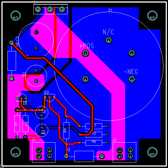
I’m using an IR IRFP9140N in place of Q1. I also replaced D2 with a 56V TVS from ON semi, 1.5KE56A. I used 56V because the LMD18245 motor driver IC I have has a continuous rating of 55V and an absolute max of 60V. I also oversized the output capacitor just to be on the safe side since I had some big ones laying around anyway. They are 22000uF 100V Panasonics. They are overkill, the voltage is rock-solid even when the motors are running at full clip. I wanted to be able to recycle the boards though if I ever upgrade to a bigger machine and have bigger motors. Here’s the layout for my circuit:
Opto-isolated Parallel Interface Board
I designed this parallel interface board after killing a parallel port with a breakout board that I bought off the internet. I think it just pulled too much current from the port. I designed this board to pull the smallest amount of current from the parallel port as possible, while also providing good drive characteristics for outputs. This board is customized to my application, so the voltages and bias might not be appropriate for all. Check to make sure your inputs will work before using the values here. I couldn’t find the schematic, just the layout but it’s not too complicated to figure out if you have the datasheets for the TLP2631 and the SN74LS244N. › Continue reading
Build a spot welder from a battery charger
I ran across a battery charger a while ago that was collecting dust. I looked inside and saw the transformer, heatsinks, high current bridge rectifier and SCR and knew I could do something with it. So I turned it into a spot welder.
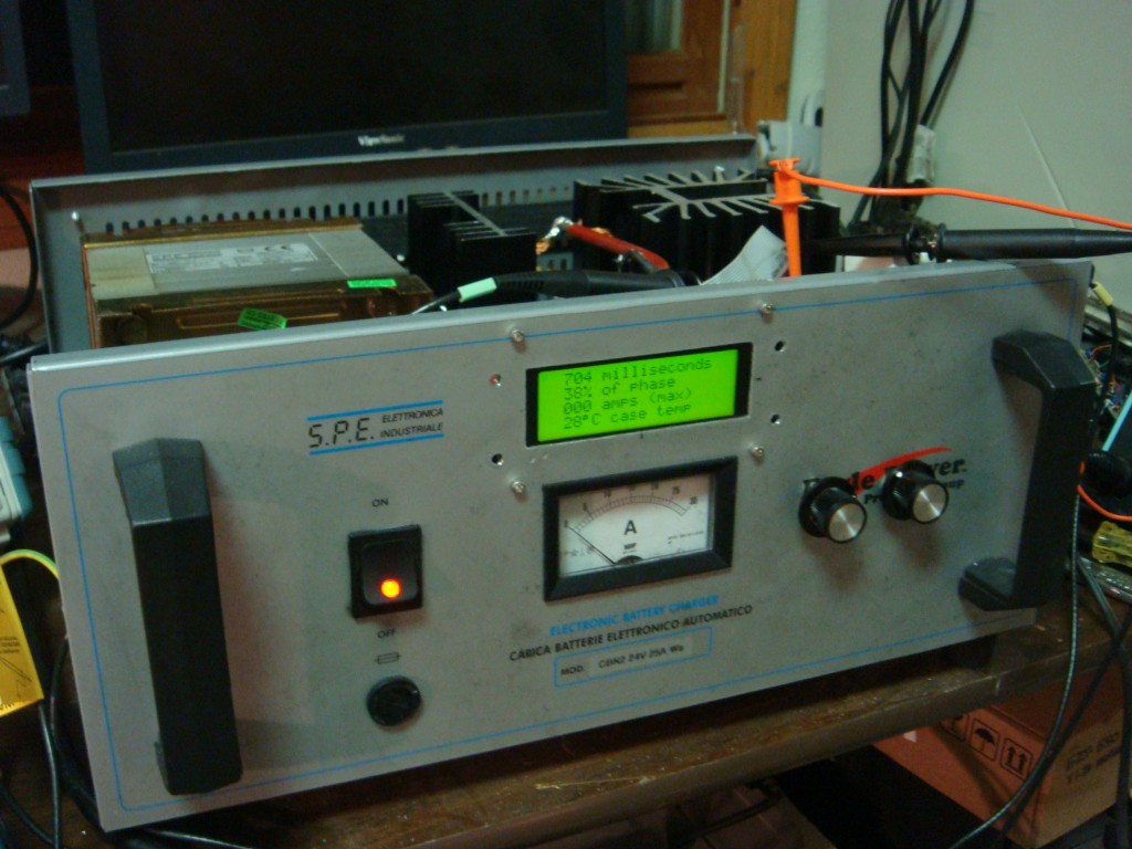
I originally intended this project to weld thin sheetmetal tabs to stuff to act as solder tabs. The project has not been as easy as I originally thought though. (It also suffered some scope creep) It’s my first crack at 5V logic mixed with line AC voltage, and for rolling my own power supply. I used a step-down transformer, bridge regulator and a capacitor to feed an LDO regulator for the control circuit. With the low current draw of the controller, the voltage input to the regulator was relatively free from any ripple thanks to the capacitor.
I ended up frying a processor, LCD, and a couple other components due to a dumb move while troubleshooting the circuit, and overlooking a capacitor’s voltage rating. 120VAC will eat 5V stuff for lunch.
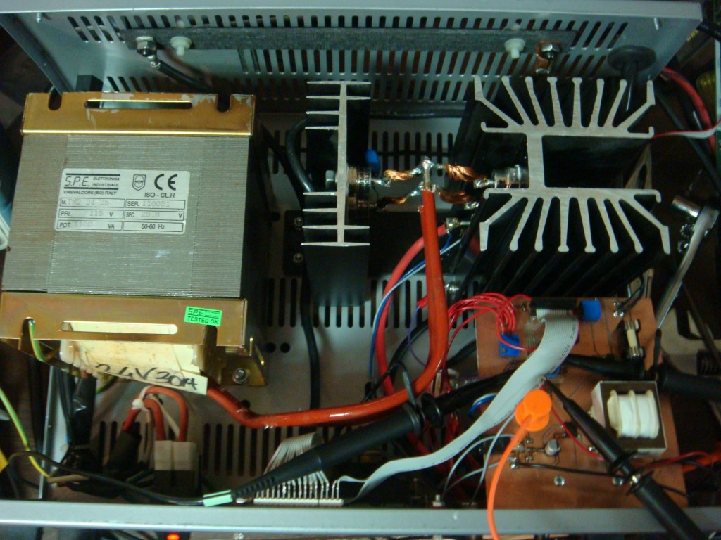
The control circuit basically modulates the SCR, which is hooked up to the output of the bridge rectifier after a step-down transformer. The controller allows for adjustment of duration of the weld and amount of the rectified AC phase that is delivered to the workpiece. The controller holds off the SCR until a pre-determined time of each half phase to control power delivery. An analog comparator detects the zero point of the phase for timing purposes, via a seperate bridge rectifier that has it’s ouput fed through a large resistor to the comparator. A zener clamps the current-limited voltage at 4.8V so as not to damage the micro’s input. A high-to-low transition on the comparator triggers the zero crossing timer. The threshhold voltage is adjustable by an on-board pot.
I also added an Allegro hall effect current sensor that I had lying around from my alternator current sense project. It’s overkill, but it measures the amount of peak current being delivered and displays it on the LCD.
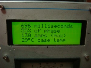
The controller is an ATmega88PA running at 8Mhz. Firmware is written in C with AVRStudio and AVR-GCC. The micro reads the power and duration settings, displays that on the LCD, along with the max current for the last weld cycle and the temperature of the mega’s on-chip sensor. The controller also handles timing duties, zero crossing detection, and control of the SCR gate. The gate is fired by a P-channel MOSFET, with the FET’s gate driven by an NPN BJT on one of the micro’s pins. A footswitch is used as input to the micro to trigger a weld cycle. Both the footswitch input and the zero crossings are buffered by a simple three-sample debouncing routine to prevent erroneous triggers. The system also checks for the footswitch input on power up and after the weld cycle is complete, and waits if the footswitch is down with a message on the LCD to release the footswitch. This allows for safety as well as eliminating any unintended re-triggers at very short durations. Duration is adjustable from roughly one ac cycle to 60 cycles (1 sec). Power control allows from 5% to 95% of each half phase to be delivered to the workpiece.
The SCR’s cathode voltage is available at PORTC2 as a 10:1 voltage divider, and clamped with a zener to prevent damage to the micro. I didn’t need it, so it’s not used in the code.
I’ve also added a power resistor to the output to limit current. I used carbon-carbon as a power resistor (I work in a carbon plant) since it’s free and power resistors are expensive. You only need a few tenths of an ohm to limit the current to a level that won’t destroy the diodes and SCR. I’m overdriving mine at about 130A maximum. It seems to handle it fine for the short bursts. [Edit: 130A isn’t enough though. I may rewire so the diodes/SCR are on the input side and push the current higher by removing or modifying the resistor. Pressure of the electrodes on the joint is also important, still figuring that out.]
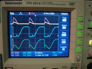
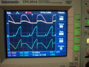
Here’s some drive waveforms: yellow is the output voltage (it’s at 50V/div so it looks small), purple is the output current measured by the hall sensor, blue is the FET’s gate that turns on the SCR, and green is the bridge voltage.
This project has got me thinking about modifying my old “buzzbox” AC welder. I’ve got some big capacitors and IGBTs from a couple old motor drives that could give me a really nice TIG welding power supply. I think I’ve read you can weld high frequency (1-2kHz?) square-wave without needing any HF section. If I remember right square-wave with a positive DC offset is sort of the ultimate TIG welder. Anybody with comments or information about that feel free to drop me a line.
Continue reading for the schematic, PCB layout, and code.
References: Miller Resistance Spot Welding
MAX4173 Current sense amplifier
I just built a current sensing application based on a MAX4173. I am suitably impressed with this device. It is extremely versatile and cheap. The MAX4173 allows you to measure the current across a sense resistor with a 28V common-mode range and provides a ground-referenced output proportional to the current across the resistor. I will probably be using one on most of my projects from now on since I do a lot of prototype work and having a cheap and easy way to sense current draw is pretty useful.
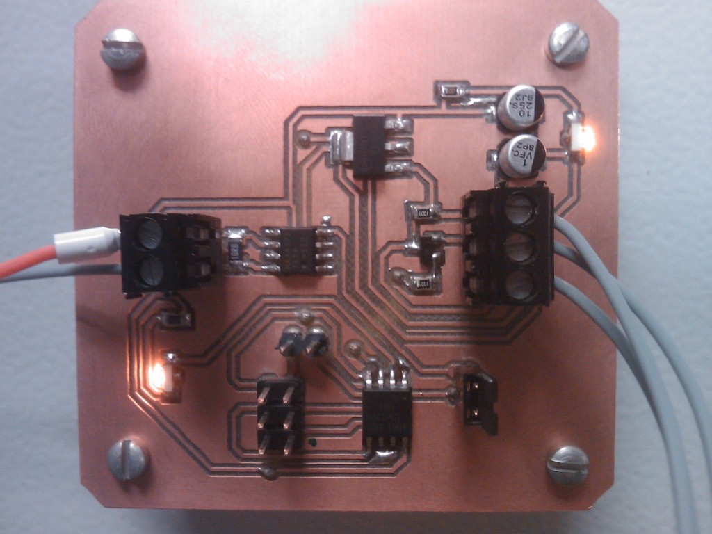
The MAX4173 is available in either an SOT23 or SO8 package, and only requires a decoupling capacitor and a sense resistor to operate. There are three different preset gains available so by combining that with the sense resistor value you can achieve a variety of current ranges.
I used the device in a 4-20mA control loop, with a 20X gain and a 10Ω resistor for a 0.8-4V output into an ATtiny 13’s ADC with a 5V reference. The 10Ω sense resistor is small enough that the loop won’t be affected and large enough to provide good signal range and sensitivity.
For future projects I will probably be using the higher gain version with a smaller sense resistor on the input power line and just leave the MAX4173 output on a header for diagnostic measurement if I don’t have a spare ADC pin. This will limit circuit loading but provide an output for measuring actual circuit current draw.
There is another similar version of the MAX4173, the MAX4080. It can handle higher common-mode voltages and bidirectional current. It’s also a bit more accurate than the 4173, but I haven’t tried it out yet.
LED backlit desk sign
I was messing around a while ago with my CNC and some of the various engraving bits I’ve tried for routing PCB traces. I had a piece of acrylic lying around, so I made myself a sign for my desk at work. I don’t really have that job title, it’s technically “intern” since I’m doing the college thing; but it would be my title if a job title was based on what you did. The description next to my name in the office’s roster is actually “special projects”, but it didn’t sound as interesting.
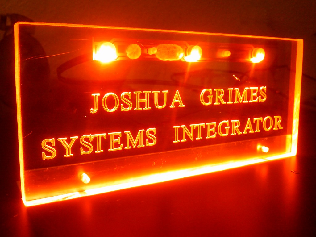
I used a NUD4001 constant-current LED driver from ON Semiconductor and some OSRAM SideLEDs. The NUD4001 is really quick and easy to implement as it only requires an external resistor to set the current level. The unit is fused, and powered by a 9V AC/DC wall wart. I tried a couple different colors, but this amber looked the best.
As a side note, I really like using ON semiconductor parts. They have excellent datasheets that usually have really good examples.
Turn signals for a trailer
I’ve been working intermittently on a project to come up with a way to add turn signals to the side of a trailer without needing any extra wiring from the truck. The way people normally do this is by tapping the side markers into the turn signal wires. However, that makes the side markers turn on and off with the brakes which makes for a confusing signal. There is no shortage of patents for adding this type of capability, but they usually require a unique transmitter aboard the truck that communicates with another unique receiver on the trailer. Since the 6 pin standard is ubiquitous, that type of system will likely not be available or popular for some time. I didn’t want to add any special hardware to the truck either. So I’ve been working on a solution that taps into the trailer’s main electrical harness and creates an extra side turn signal for each side of the trailer and also functions as a clearance light.
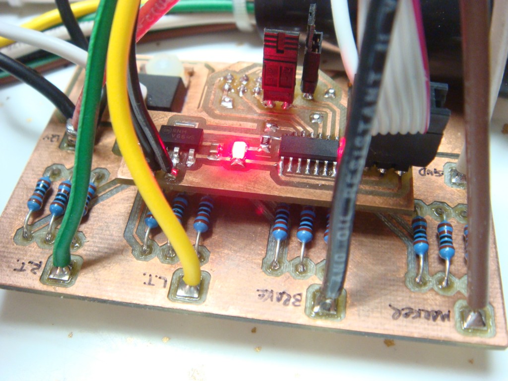
You can use any standard clearance light and it will function as a clearance light when the lights are on, and also flash that light when the appropriate turn signal is on. The brakes will not cause the side markers to flash. You can add new lights, or simply intercept the wiring to existing clearance lights. The only modification is to the trailer, and it will work the same for any truck. The only requirement is that the trailer has electric brakes and the truck has a brake controller.
My code is running on an ATtiny24, on a board I prototyped just for this. I built an in-line harness for testing that passes the signals from the 6 pin connector to the trailer, but taps into those signals for the logic. My device has two standard LED clearance lamps attached as left and right turn signals for testing. This system is an add-on to the existing trailer wiring, so in the event of a failure nothing is compromised.
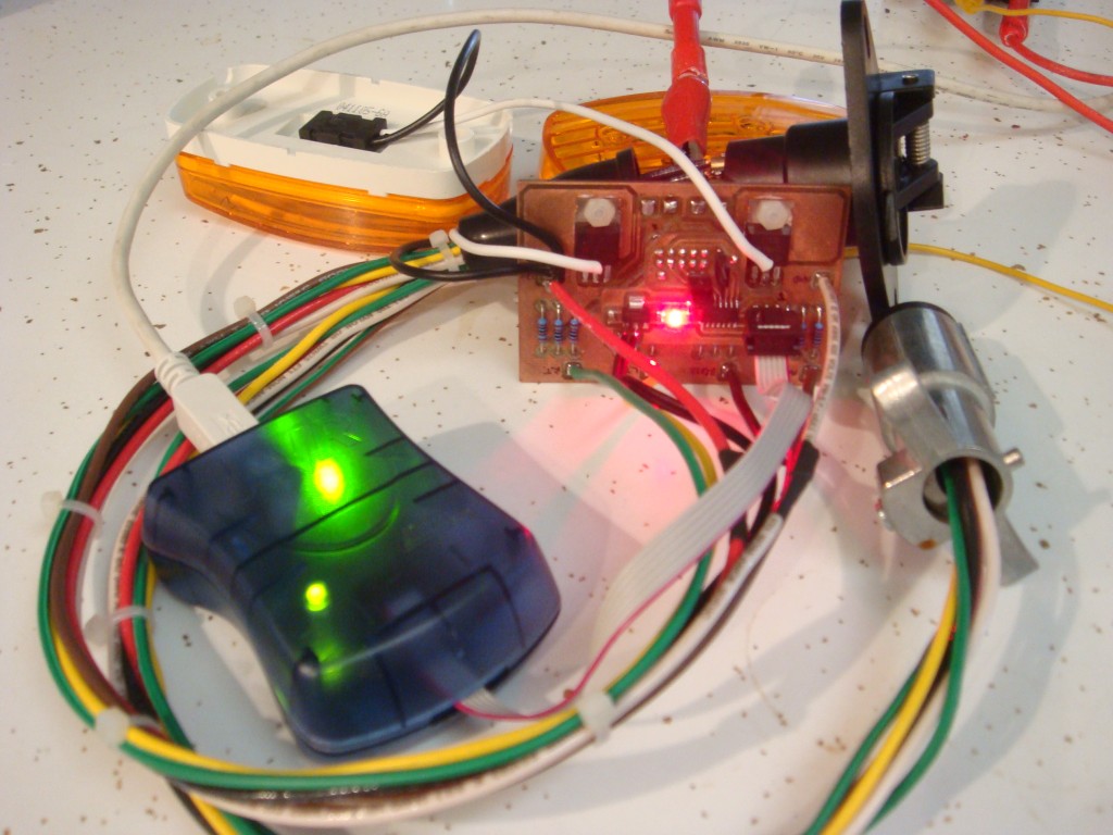
It has been tough getting this working, as there’s not exactly a manual for how the truck and the brake controller handle the signals. It’s taken a few months, as evidenced by the tarnished PCB. If I remember right I made it this summer.
Xbox 360 red lights issue
A few days ago (just in time for Christmas break) my Xbox 360 started crashing and then gave me 3 red lights, indicating a hardware failure. This is really lame, since I just got hooked on Forza 3, and now I won’t be able to play it over my break from school and work. Thanks Xbox.
I looked up the reason for the red lights, since I can usually find a way to fix stuff. The consensus is that the GPU interface suffered a manufacturing problem due to lead-free solder where the BGA solder balls develop cracks over time. Sounds reasonable. The “fixes” seem to either be reballing the GPU (expensive) or a supposed reflow process that just overheats the GPU.
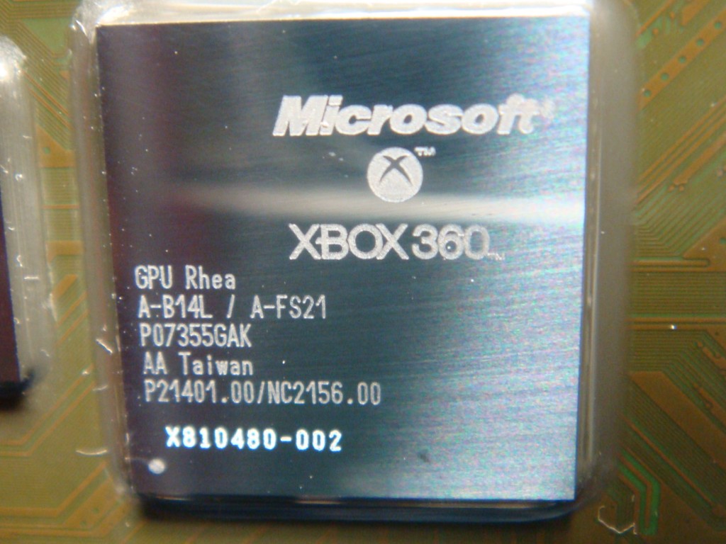
I tried this one first, since there wasn’t much to lose anyway. The theory is that you can reflow the BGA solder balls and restore electrical contact between the GPU and the PCB by just overheating the GPU. I am pretty skeptical that this is possible, as I don’t think a chip is capable of heating itself to the 320+ °F necessary for solder to melt and flow without damaging itself. Transistors tend to flow a lot of current when they get hot, which would likely damage the processor. At any rate, I tried it. It worked for a day. I wish I would have instrumented the GPU so I knew the peak temperature, but I forgot.
So then I tried to actually reflow the GPU. I tried 5% rosin no-clean flux, and saturated the GPU/PCB interface. I preheated the board to 300°F by setting it on a heated stir plate. I had a fine-gauge K-type thermocouple tucked just under the die so that I could measure the temperature. I heated the die with a hot-air station to 420°F over 2 minutes, and then increased to 450-475°F and held for about 30 seconds.
After the board cooled, I put it back together and plugged it in. Still got three red lights. I took it back apart again and did the same thing to the CPU, but still had the same problem. Then I tried again with 30% rosin flux and slightly higher temperatures. Same three red lights. I suppose the board is junk now, but I still am curious why it worked again after heating the board up a little bit from overheating the GPU. It tells me that most of the fixes out there for “reflowing” aren’t actually doing so, instead they are just creating enough stress on the PCB to fix whatever joint is intermittent. For example, one person supposedly reflowed his entire board in his kitchen oven. I’m not an expert in PCB manufacturing, but if the whole board is at reflow temperature, won’t the RAM chips (and most components) on the bottom side just fall off? There can’t be enough surface tension from the solder balls to actually hold the chip in place upside down.
I did some more digging and found out that you can in fact get error codes without video out. There is a lot of good information at xbox-experts.com. I found out that I have a “bridged solder joint/short GPU/HANA”. I wonder if it’s because of my novice “reflow” skills. I can solder with the best of them, but this is totally different. Wish I had started there first.
That’s one of the funny things about modern manufacturing- it makes something hard look really easy.
References:
http://www.altera.com/literature/an/an353.pdf
http://www.altera.com/literature/wp/wp_chmfgrelldfr.pdf
http://www.altera.com/literature/an/an081.pdf
Moisture Meter for Plants
My wife suggested to me the idea of a visual indication for the soil moisture level in a houseplant (that is, before the brown leaves indication). We hadn’t seen anything like it in stores. So I made a prototype which worked quite nicely, and then we found that they were already available online through retailers like Amazon. Here’s the prototype I made:
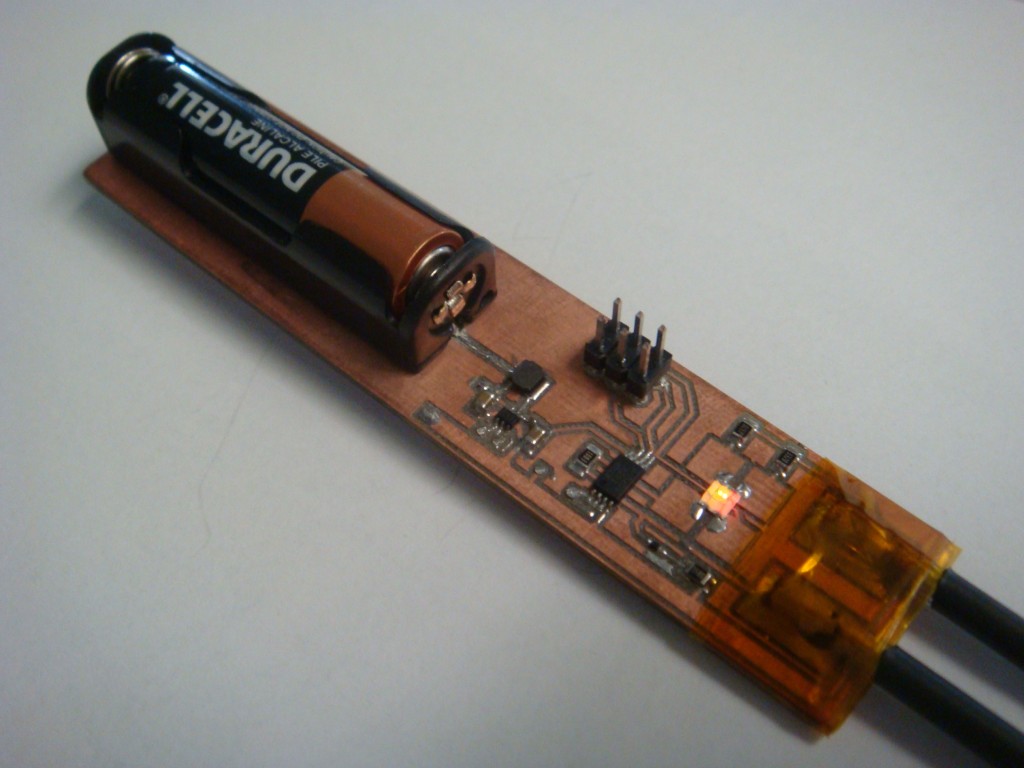
It has two probes at one end that get inserted into the soil, and the LED then flashes either red, yellow, or green depending on the moisture content of the soil. It all runs on one AAA battery for about a month, but that could be improved by reducing the flash time and ADC sampling. The code for the prototype flashes the LED every second or two and samples every time.
Strain-Guage based Pressure Sensor
I just finished building a self-contained pressure sensing device using a MEMS strain-guage type sensor from Measurement Specialties. Single phase AC goes in one side, and a 0.5V-4.5V signal proportional to pressure input comes out the other side. The sensor has a rated max of 5″ of water.
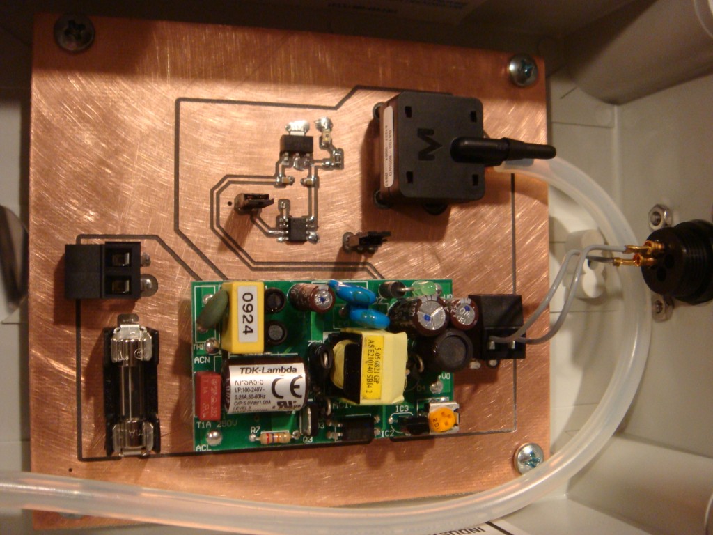
The circuit is simple enough, the AC goes through a fuse and into a AC-DC converter. The output is regulated by a 5V regulator, which powers an op-amp and the sensor. The op-amp buffers the output of the sensor. I used a MAX4242 op-amp, as it can run on less than 5V, and has rail to rail inputs and outputs. This keeps my signal in the CMR range.
I have used products from Measurement Specialties in the past, and they seem to be very good products for the money. I have some of their button load cells which were very affordable and also have about twice the output signal (mV/V) of similar load cells from Omega or Futek.
0.008″ PCB trace isolation on my CNC
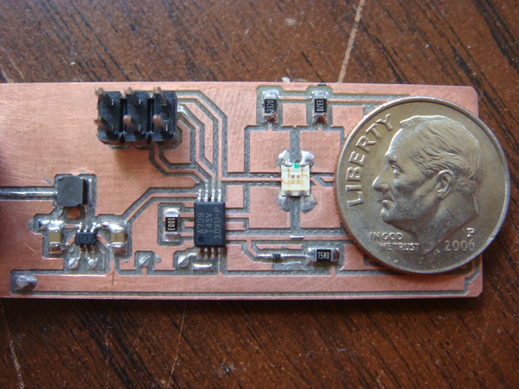
Due to a new design that I am working on, I needed to use a component from TI that only came in a 6SC70 package. It’s a boost converter (TPS61221) that operates from an input voltage as low as 0.7V and has 80% or better efficiency in the 1-10mA range. It’s trimmed at 3.3V, which I’m using to run an ATtiny45V. The ATtiny45 comes in a fine-pitch package as well, an 8TSSOP that requires 0.009″ isolation between pads. I haven’t been able to get much better than 0.020″ with the tooling I have, so I have been looking for alternatives.
I found some mechanical engraving bits at Think & Tinker which is actually here in Colorado at Palmer Lake. Their URL descriptor says they offer “Instrument and PCB prototyping equipment”. They also sell carbide engraving bits, and the particular one I selected was the 60° cutter, part number #EM2E8-0625-60V. The bits came in a nice container and are labelled as having a 0.005″ tip. The shipping was also wicked fast. Granted, it’s only a few hours away from my location but I ordered them and got them in the next day.
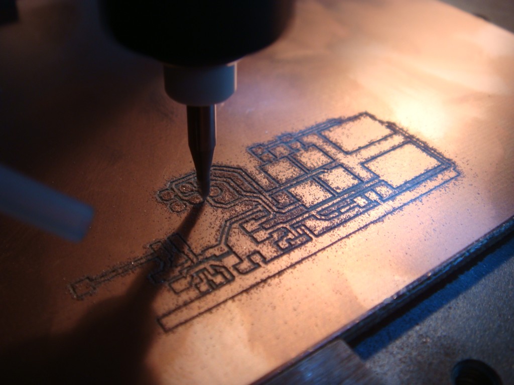
I’ve only cut one board, but I’m really happy with the results. I successfully achieved 0.008″ isolation between the pads of the devices, and now I can finally route traces inbetween the pads of 0.1″ headers. I couldn’t do that before.
MEMS Accelerometers
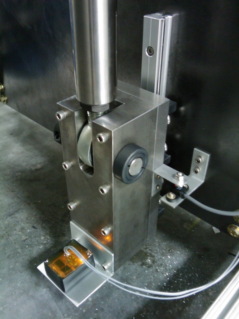
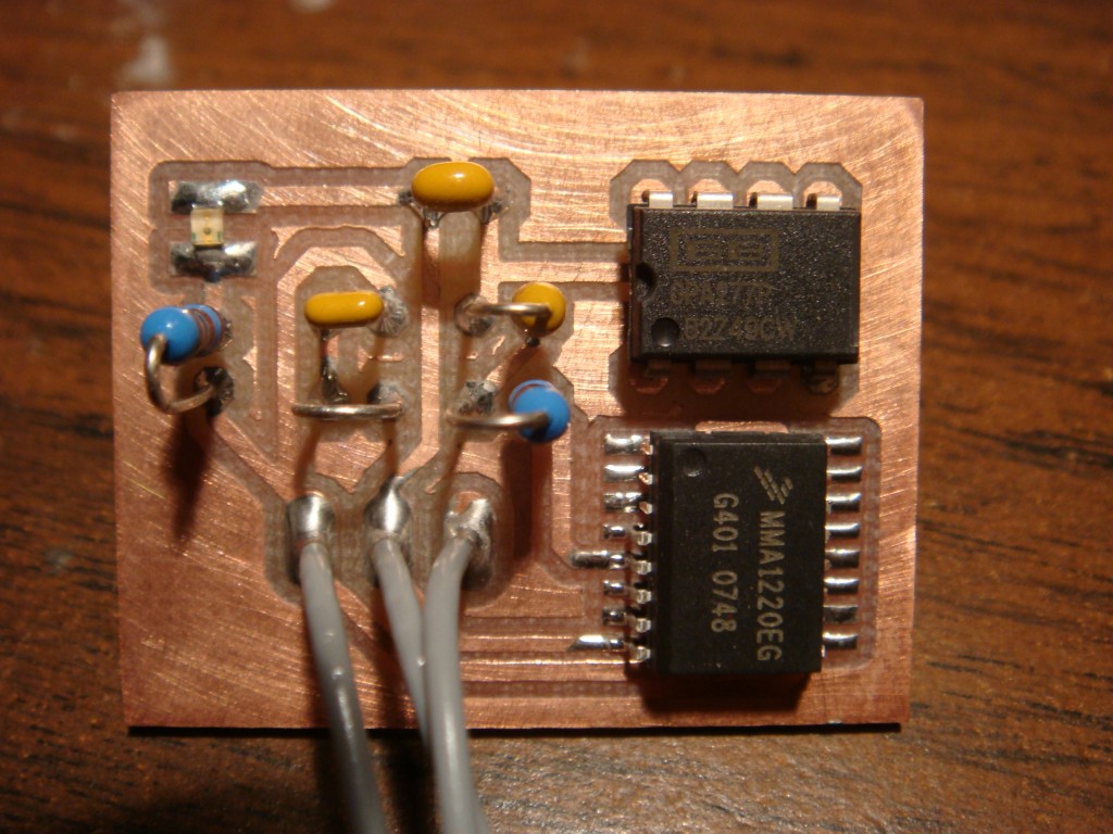
I recently messed with some accelerometers in order to cancel out dead weight in a load cell application. These MEMS (microelectromechanical systems) devices are really handy. They are incredibly small, they have very modest power requirements, and are typically in a standard IC package. The device that I ended up using was a Freescale MMA1220EG. It offers an on-board amplified output and only requires three external components. It uses 5VDC at 5mA, and has a +/- 8g range. The 0g offset is 2.5V and moves from that point at 250mV/g.
I built a simple PCB that mounted the accelerometer and a filter along with an op-amp as a buffer to drive the output and send it down a run of wire. It worked so well I’ve been trying to think up something else to put one on.
Other Stuff
Recent Posts
- 6CY7 dual triode valve amplifier
- Air quality sensor (TVOC and eqCO2)
- Automotive rear fill “surround sound” with Boss DD-3
- Spring tester / weight scale
- Ducati 749/999 Tail Light
- Instruments for the GSXR
- Light pipe tail light for the GSXR
- M17x 6990m / 6970m overheating
- PAR / Spectrum analyzer
- Acrylic polishing and scratch removal
Archives
- May 2019 (2)
- April 2017 (3)
- October 2015 (1)
- May 2015 (1)
- March 2014 (2)
- December 2013 (1)
- July 2013 (1)
- November 2012 (1)
- October 2012 (4)
- September 2012 (1)
- August 2012 (3)
- June 2012 (1)
- March 2012 (1)
- February 2012 (1)
- January 2012 (1)
- October 2011 (3)
- July 2011 (1)
- June 2011 (3)
- May 2011 (2)
- April 2011 (1)
- December 2010 (1)
- August 2010 (1)
- July 2010 (3)
- April 2010 (2)
- March 2010 (2)
- January 2010 (2)
- December 2009 (2)
- October 2009 (2)
- September 2009 (1)
- August 2009 (15)