Instruments for the GSXR
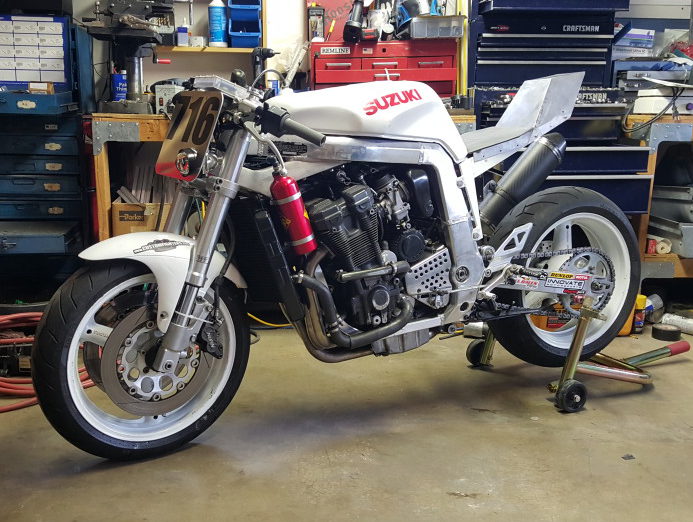
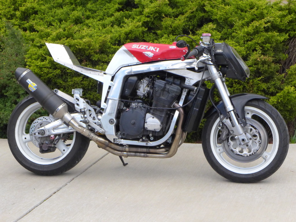
Since the GSXR is now a street fighter the factory gauges won’t do, and I wanted something I could log air/fuel ratios with so I can jet the bike. I went a little overboard making a new dash.
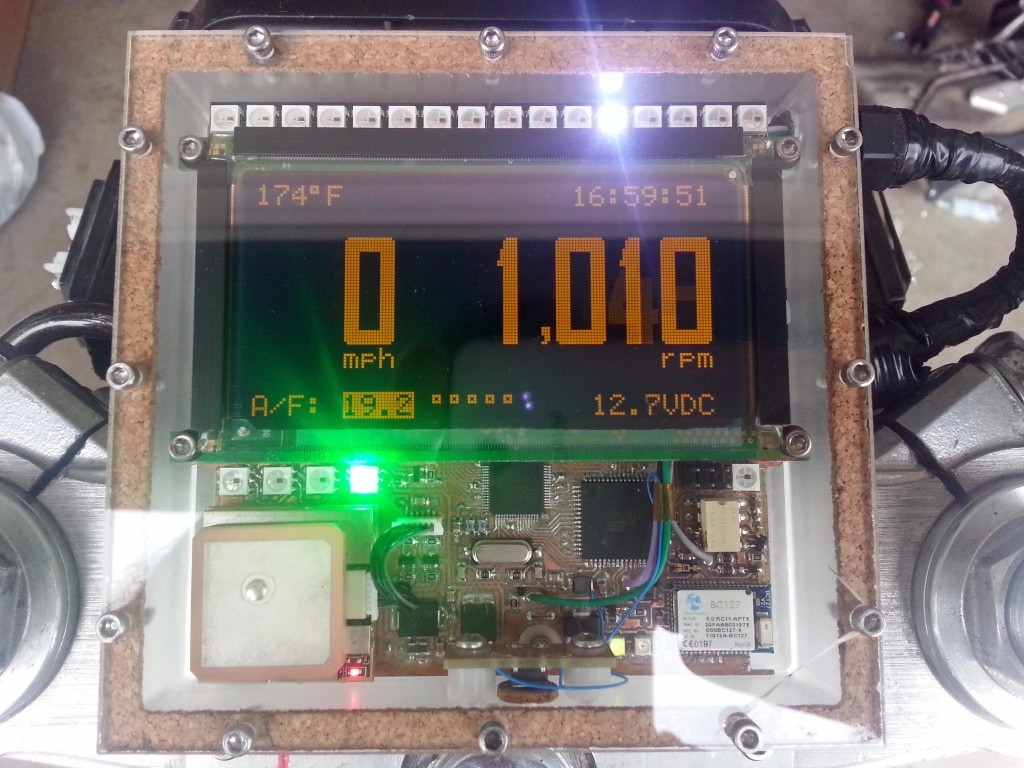
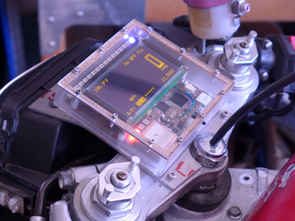
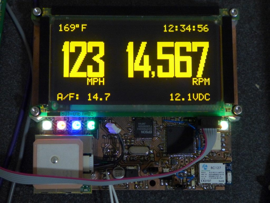
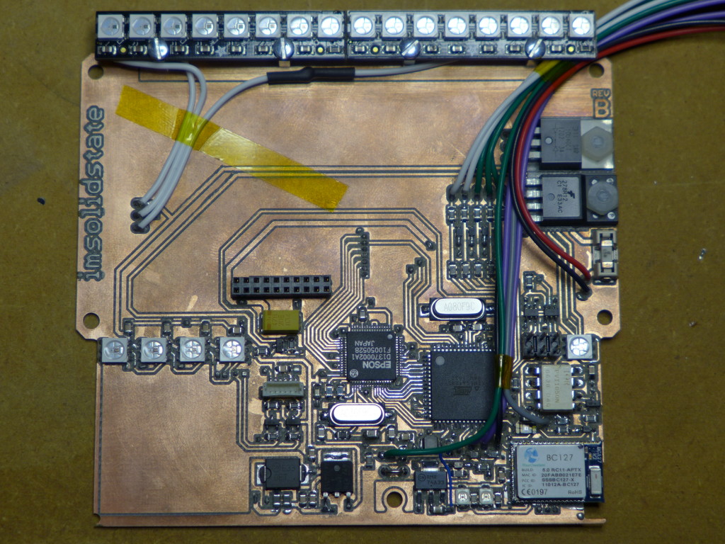
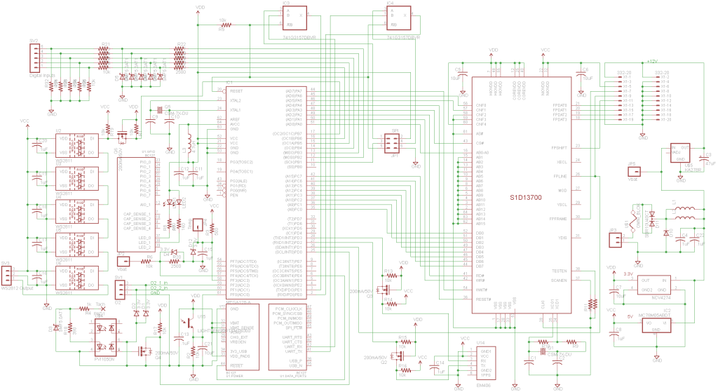
I had a Planar 160×80 EL graphic display that’s been in my parts bin for years that I’ve always wanted to use, and this was perfect. Unfortunately it doesn’t have a controller so I had to interface it to the CPU with an Epson S1D13700 graphic controller. The display indicates speed from a GPS module, air/fuel ratios from the wideband O2 sensor, engine temp, battery voltage, time from GPS, and RPM. I used a light sensor to sense ambient brightness levels and dim the display by changing TC/R in the graphics controller. The refresh of the display is high enough to allow a large dimming range without flickering. The EL display can be refreshed at up to 240Hz. The light sensor also controls the brightness of the bar graph and indicator LEDs. A BC127 bluetooth module allows datalogging via SPP, and I might eventually get around to displaying SMS messages from my phone on the display which was one of the design goals but isn’t done yet.
An IR optoisolator senses RPM pulses from the magnetic pickup and protects the system from ignition noise. Addressable LEDs function as indicator lights as well as forming the bar graph at the top of the display. The bar graph can display RPM, battery voltage, engine temp, or A/F ratios depending on the current mode which is selected by a button on the side of the housing. The bar graph is also a two stage shift light which overrides any display mode and goes to full brightness with two different colors to indicate high RPM for shifting. A highlight box on the graphics layer shows which mode is currently active and the graphic and text layers are XOR’ed. I also made a custom bitmapped font I thought went well with the display size and the amount of characters.
I did have problems with the cursor randomly flashing around the display since you can’t actually turn the cursor off with the S1D13700, so I had to implement a buffered graphics display. Data is collected from the various sensors and serial interfaces which updates the graphic frame buffer, and then the buffer is written to the display.
An ATmega128L runs the system, and the logic was all written in C. This will hopefully be my last big project with an AVR (especially the 128), as I am trying to migrate to ARM for bigger projects.
I made the housing from cast acrylic on my CNC. The base is milled out 1″ sheet. I made the PCBs on my CNC as well. Here is the schematic which I think is current, source code and a video of the whole thing in action.
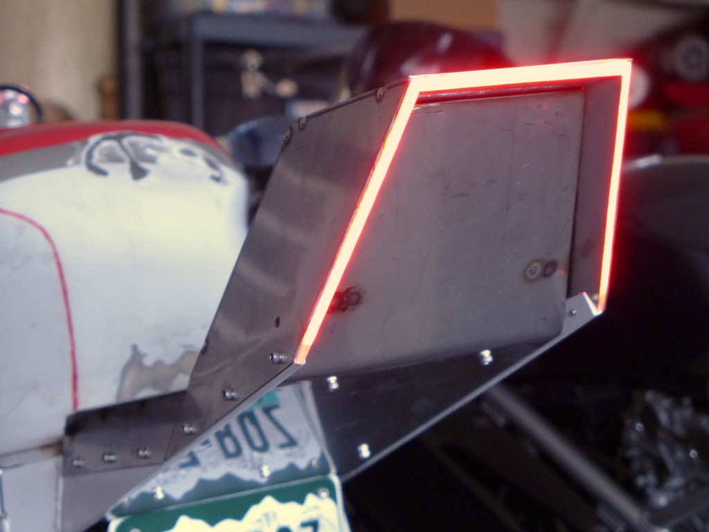
Check out my tail light here:
14 Comments to Instruments for the GSXR
Leave a Reply
Other Stuff
Recent Posts
- 6CY7 dual triode valve amplifier
- Air quality sensor (TVOC and eqCO2)
- Automotive rear fill “surround sound” with Boss DD-3
- Spring tester / weight scale
- Ducati 749/999 Tail Light
- Instruments for the GSXR
- Light pipe tail light for the GSXR
- M17x 6990m / 6970m overheating
- PAR / Spectrum analyzer
- Acrylic polishing and scratch removal
Archives
- May 2019 (2)
- April 2017 (3)
- October 2015 (1)
- May 2015 (1)
- March 2014 (2)
- December 2013 (1)
- July 2013 (1)
- November 2012 (1)
- October 2012 (4)
- September 2012 (1)
- August 2012 (3)
- June 2012 (1)
- March 2012 (1)
- February 2012 (1)
- January 2012 (1)
- October 2011 (3)
- July 2011 (1)
- June 2011 (3)
- May 2011 (2)
- April 2011 (1)
- December 2010 (1)
- August 2010 (1)
- July 2010 (3)
- April 2010 (2)
- March 2010 (2)
- January 2010 (2)
- December 2009 (2)
- October 2009 (2)
- September 2009 (1)
- August 2009 (15)

Hi Josh,
Awesome build. We stumbled upon it and will featurs this on the Hackaday blog soon.
[…] Motorcycle custom instrument panel – [Link] […]
[…] Motorcycle custom instrument panel – [Link] […]
[…] Motorcycle custom instrument panel – [Link] […]
DUDE!!!!!!!!!!!! That is one AWESOME ride!!!!!!!
This is fantastic! I use this engine on my race car, as do a lot of other amateur racers in the US, so this is interesting to many people. My 2008 GSX-R1000 doesn’t have a standard OBD-II connector– how did you to the other side of the Bluetooth connection, the one that’s wired to the ECU?
Shitty bike build
Thanks Steve!
Then show me your build, internet armchair critic.
JJLudemann – My bike is a ’92 so it doesn’t have bluetooth. I send data from the sensors via the AVR to the bluetooth module, which then connects to my phone. I don’t connect to the ECU at all. I use the ignition pickup to sense RPM and the AVR’s ADC for things like engine temp. Your ECU should still have some kind of OBD complaint com port, it’s probably a 3-wire connector.
Hey man great project any way you can share the schematic and code, im hopping to do the same.
Hi,
Very impressive. I also would be interested to do the same on my GSXR. Can you send me the shopping list, schematic and code ?
Thanks 😉
Love the build. Most excellent. Life your other work.
Don’t get mad at Togo. He’s probably sad that his Game Boy died and he can’t scarf his neighbor’s WiFi down in his mom’s basement after the neighbor added a passcode. Life’s tough for Togo at 32 and working as a part time janitor at Wendy’s.
Hi, can you make this for an aprilia rsv 1000 mille?How much would it cost?(plus oil pres. sensor,2 lambda sensor for air fuel ratio meter! Tibor.